Transcription of OPERATION MANUAL - daikinac.com
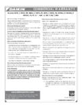
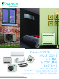
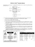
1 OPERATION MANUAL . Wireless Remote Controller Kit MODEL. BRC7E83. Read these instructions carefully before installation. Keep this MANUAL in a handy place for future reference. This MANUAL should be left with the equipment owner. 2. 1. ON OFF ON OFF. 8. TEMP. 3. H M L H M L TIME 11. DOWN 10. F F. UP UP. 6. DOWN. FAN. 13. FAN. 4 RESERVE CANCEL. 9. hr. hr. TIMER 12. 2 hr. hr. MODE 15. SWING 14. 5. 16. TEST TEST. 7 TEST 17. Fig. 1-2. The situation which opened the front cover of the remote control Fig. 1-1. 24. 22 23. 25. Fig. 2. 19 21 20 18. COOL/HEAT CHANGEOVER. REMOTE CONTROL SWITCH. Fig. 1-3. 3. CONTENTS Do not touch the switch with wet fingers. Touching a switch with wet fingers can cause electric shock. ILLUSTRATIONS ..3 Do not operate the air conditioner with a wet hand. 1. SAFETY CONSIDERATIONS ..4 Otherwise, you could receive an electric shock.
2 2. NAMES AND FUNCTIONS OF THE OPERATING. SECTION ..4 CAUTION. 3. HANDLING FOR WIRELESS REMOTE. Do not use the air conditioner for other purposes. In order to avoid any quality deterioration, do not use the unit 4. OPERATION PROCEDURE ..6 for cooling precision instruments, food, plants, animals or 5. NOT MALFUNCTION OF THE AIR CONDITIONER ..9 works of art. 6. HOW TO DIAGNOSE TROUBLE To avoid oxygen deficiency, ventilate the room suffi- ciently if equipment with burner is used together with the air conditioner. Do not allow a child to mount on the unit or avoid placing any object on it. 1. SAFETY CONSIDERATIONS Falling or tumbling may result in injury. Please read these SAFETY CONSIDERATIONS carefully Do not let children play on and around the unit. before installing air conditioning equipment and be sure to If they touch the unit carelessly, it may result in injury.
3 Install it correctly. After completing the installation, make sure Do not place a flower vase and anything containing that the unit operates properly during the start-up OPERATION . water. Please instruct the customer on how to operate the unit and Water may enter the unit, causing an electric shock or fire. keep it maintained. Do not operate the air conditioner when using a room Also, inform customers that they should store this OPERATION fumigation - type insecticide. MANUAL along with the installation MANUAL for future reference. Failure to observe could cause the chemicals to become This air conditioner comes under the term appliances not deposited in the unit, which could endanger the health of accessible to the general public . those who are hypersensitive to chemicals. Meaning of warning, caution and note symbols.
4 Never use flammable spray such as hair spray, lacquer WARNING .. Indication a potentially hazardous situa- or paint near the unit. tion which, if not avoided, could result in It may cause a fire. death or serious injury. CAUTION .. Indication a potentially hazardous situa- tion which, if not avoided, may result in minor or moderate injury. It may also be 2. NAMES AND FUNCTIONS OF THE. sued to alert against unsafe practices. OPERATING SECTION (Fig. 1-1~3, 2). situation that may result in equip- ment or property-damage-only accidents. DISPLAY I (SIGNAL TRANSMISSION). Keep these warning sheets handy so that you can refer to 1. them if needed. This lights up when a signal is being transmitted. Also, if this equipment is transferred to a new user, make sure to DISPLAY . hand over this OPERATION MANUAL to the new user. ( OPERATION MODE).
5 2. This display shows the current OPERATION MODE. For WARNING VRV system, is not installed. It is not good for your health to expose your body to the H M L. air flow for a long time. DISPLAY (SET TEMPERATURE). 3 F. In order to avoid electric shock, fire or injury, or if you This display shows the set temperature. detect any abnormality such as smell of fire, turn off power and call your dealer for instructions. DISPLAY hr. hr. (PROGRAMMED TIME). Ask your dealer for installation of the air conditioner. 4 This display shows PROGRAMMED TIME of the sys- Incomplete installation performed by yourself may result in a tem start or stop. water leakage, electric shock, and fire. Ask your dealer for improvement, repair, and maintenance. DISPLAY (AIR FLOW FLAP). 5. Incomplete improvement, repair, and maintenance may Refer to page 7.
6 Result in a water leakage, electric shock, and fire. DISPLAY (FAN SPEED). Do not put a finger, a rod or other objects into the air inlet 6. This display shows the set fan speed. or outlet. As the fan is rotating at high speed, it will cause injury. DISPLAY TEST (INSPECTION/ TEST OPERA- Ask your dealer to move and reinstall the air conditioner. TION). 7. Incomplete installation may result in a water leakage, electric When the INSPECTION/TEST OPERATION BUTTON. shock, and fire. is pressed, the display shows the system mode is in. 4. ON/OFF BUTTON NOTE. 8 Press the button and the system will start. Press the For the sake of explanation, all indications are shown on the button again and the system will stop. display in Fig. 1-1 contrary to actual running situations. FAN SPEED CONTROL BUTTON Fig. 1-2 shows the remote controller with the front cover 9 Press this button to select the fan speed, HIGH or LOW, opened.
7 Of your choice. Fig. 2 shows this remote controller can be used in conjunc- TEMPERATURE SETTING BUTTON tion with the one provided with the VRV system. Use this button for SETTING TEMPERATURE. If the air filter cleaning time indicator lamp lights up, clean 10 the air filter as explained in the OPERATION MANUAL provided (Operates with the front cover of the remote controller closed.) with the indoor unit. After cleaning and reinstalling the air filter, press the filter PROGRAMMING TIMER BUTTON. sign reset button on the remote controller. The air filter 11 Use this button for programming START and/or STOP cleaning time indicator lamp on the receiver will go out. time. (Operates with the front cover of the remote con- The DEFROST lamp will flash when the power is turned on. troller opened.). This is not a malfunction. TIMER MODE START/STOP BUTTON.
8 12. Refer to page 8. TIMER RESERVE/CANCEL BUTTON. 13. Refer to page 8. 3. HANDLING FOR WIRELESS REMOTE. AIR FLOW DIRECTION ADJUST BUTTON CONTROLLER. 14. Refer to page 7. Precautions in handling remote controller OPERATION MODE SELECTOR BUTTON Direct the transmitting part of the remote controller to 15. Press this button to select OPERATION MODE. the receiving part of the air conditioner. FILTER SIGN RESET BUTTON If something blocks the transmitting and receiving path of the indoor unit and the remote controller as curtains, it will not 16 Refer to the section of MAINTENANCE in the OPERATION operate. MANUAL attached to the indoor unit. INSPECTION/TEST OPERATION BUTTON. 17 This button is pressed for inspection or test OPERATION . Do not use for normal OPERATION . EMERGENCY OPERATION SWITCH. 18 This switch is readily used if the remote controller does not work.
9 Receiver 2 short beeps from the receiver RECEIVER indicates that the transmission 19. This receives the signals from the remote controller. is properly done. OPERATING INDICATOR LAMP (Red). Transmitting distance is approximately 23 20 This lamp stays lit while the air conditioner runs. It flashes when the unit is in trouble. Do not drop or get it wet. It may be damaged. TIMER INDICATOR LAMP (Green). 21 Never press the button of the remote controller with a This lamp stays lit while the timer is set. hard, pointed object. AIR FILTER CLEANING TIME INDICATOR LAMP (Red) The remote controller may be damaged. 22. Lights up when it is time to clean the air filter. Installation site DEFROST LAMP (Orange) It is possible that signals will not be received in rooms that 23 Lights up when the defrosting OPERATION has started. have electronic fluorescent lighting.
10 Please consult with the (For cooling only type this lamp does not turn on.) salesman before buying new fluorescent lights. If the remote controller operated some other electrical appa- FAN/AIR CONDITIONING SELECTOR SWITCH ratus, move that machine away or consult your dealer. 24 Set the switch to (FAN) for FAN and (A/C) Placing the remote controller in the remote controller for HEAT or COOL. holder COOL/HEAT CHANGEOVER SWITCH Install the remote controller holder to a wall or a pillar with the attached screw. (Make sure it transmits.). 25 Set the switch to (COOL) for COOL and . (HEAT) for HEAT. 5. FOR SYSTEMS WITHOUT COOL/HEAT. Placing the remote Removing the CHANGEOVER REMOTE CONTROL SWITCH. controller remote controller (Fig. 1-1~2 on page 3) . Slide from above. Pull it upward. 1 MODE OPERATION MODE SELECTOR. Press OPERATION MODE SELECTOR button several times and select the OPERATION MODE of your choice as follows.