Transcription of operation manual concrete pump
1 - 1 -1 Description_____ Description of main components_____ Description of pumping cycle_____ 52 Safety Field of application_____ Qualifications and duties of the pump operator_____ Important safety egulations_____ In general_____ Maintenance and repair_____ Working area_____ Placing_____ Minimum wall thickness and operating pressure of conveyor pipes___ 123 operation of the concrete Pump_____ In general_____ Description of the operating elements_____ First starting / test run_____ manual function of control block_____ First starting.
2 Drive cylinders_____ Spare function with fault of sensors or amplifier_____ Set up the concrete pump_____ concrete pumping_____ Start pumping_____ Pumping hints (depending on concrete quality)_____ Pumping hints (depending on machine)_____ Cleaning_____ Cleaning by suction_____ Cleaning with pressure water_____ Conversion and replacement of wear parts_____ Replacement of wear plate and wear ring_____ Replacement of conveyor pistons_____ Replacement / turning of conveyor cylinders_____ Replacement of the agitator tool_____ 23- 2 -4 Maintenance_____ General Daily After the first 50 operating hours Weekly Every 100 operating Every 500 operating Every 1000 operating Tightening torque s for
3 Lubricants_____ 275 Trouble Truck engine does not start_____ Pump unit does not start (without hydraulic pressure)_____ Pump unit stops (at maximum pressure)_____ Pump unit works with too low performance_____ Agitator does not work_____ Hydraulic oil is getting too hot_____ Faulty operations_____ Drive cylinders work with shortened stroke_____ Faulty operation of tilting cylinders_____ Delayed switch over with pressure peaks_____ Changing of stroke number is too fast / too slow_____ Grease system does not work_____ Mixing wing does rotate_____ Mixing wing does not rotate_____ 32- 3 -PREFACEB efore operating this machine please read carefully the
4 Following have tried to keep this instruction manual as short as possible in order to help you inbecoming quickly acquainted with our machines. We are, however, obliged by law to includecomplete details on the technical construction, maintenance and safety regulations, etc. So thatwe are unable to shorten this manual further. This is for your own safety, also for personsconcerned with this pump operator and all persons concerned with this machine are equally obliged to studythis manual thoroughly, not only to operate it properly and economically, but also to avoiddamage and must draw your attention to the fact that our warranty is void if your machine is not operatedand maintained according to our instructions.
5 If you have any queries or problems contact thetechnical advisers at our company. We would be pleased to help you and would enjoy hearingform parts and wear parts, or any other parts which are not supplied by the manufacturer orhis authorised representative are excluded from the warranty. For foreign products noresponsibility can be cannot be made on the manufacturer as a result of any information contained in oromitted from this manual , especially with regard to the construction and/or the assembly of to our continued efforts to improve our machines in every way.
6 Modifications are effectedfrom time to time and it could be that some changes could not be included in this manual at thetime of going to take into consideration that the present operation manual is valid for different versions ofthis pump model. Therefore it is possible that the pump version ordered by you may be differentto the technical version described in this and all spare parts are listed in a special catalogue / spare part list according to thepart numbers. For spare part orders please indicate the part number, the model and themachine manual should be regarded as an essential part of the THP-Trailer-Pump of the WaitzingerBaumaschinen GmbH company.
7 It should be kept in a safe place as a reference 4 - operation manual concrete Description of main components1 Subframe2 Frame connection for boom base3 Pedestal, reling and ladder4 Boom support5 Pump unit with main control block6 concrete delivery pipeline7 Additional water tank with water pump8 Boom base with outrigger9 Control panel10 Distributor boom11 Distribution gear box with hydraulik pumpsDescriptionoperation manual concrete 5 Description of pumping cycle1. electric motor. The control system is electric and fully automatic.
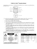
8 When using the monitoring switch aspare function can be switched on additionally which enables a continuous working of the concretepump at reduced engine speed upon breakdown of the control system or the senors. The number ofstrokes can be adjusted from minimum to maximum. The drive cylinders (1) have an automaticleakage compensation. The S-tube valve compensates the wear on the wear plate and on the wearring :Drive cylinder, right6:S-valve2:Control block7:Wear plate3:Water box8:Tilting drive4:Conveyor piston9:Conveyorclyinder5:S-valve system with agitator10:Drive cylinder, leftThe concrete pump works as follows: The tilting cylinders are in pos.
9 S13. During the pumping thepressure relief valve Y3 is closed electrically while Y4b is being started. The drive cylinders run intodirection A . The concrete in the left conveyor cylinder is pressed through the S-tube valve into theconveying line. In the right conveyor cylinder concrete is sucked from the open bore hole in thehopper. As soon as sensor S12 is switched on, Y4b stops while Y5b is being started. The drivecylinders stop and the tilting cylinders move into position C . The S-valve is now at the front of the right conveyor cylinder.
10 Sensor S14 starts Y4a (Y5b stops) and thedrive cylinders move into position B . The right conveyor piston pumps the concrete through the S-valvewhile the left one sucks the concrete out of the S-valve housing. Sensor S11 stops Y4a and Y5a shiftsthe S-valve back into position D . Thus the cycle is being 6 - operation manual concrete Safety Field of applicationThe use of this pump can bedangerous!!1. The current operating instructions must be inthe Operator must be trained and must signconfirming that he has "taken note" of theoperating The operator is obliged to behave inaccordance with the operating works Guarantee is cancelled if yourmachine is not operated and maintained inaccordance with the operating The following injuries can occur in improperuse:5.