Transcription of DS26LV31T 3V CMOS 4 回路入り差動出力ライン・ドライバ
1 DS26LV31T 3V cmos 1 TIA/EIA-422-B (RS-422) ITU-T TIA/EIA-422-B (RS-422) 5V RS-422 2V VOD EMI (50% 40mV ( ) ) ( 330 W) ESD 7kV ( I/O HBM) AC 2ns 10ns DS26C31 SOIC (SMD) 5962-985842 DC DC 3 DS26LV31T TIA/EIA-422-B ITU-T cmos cmos DS26LV31T 100 A ICC VOD (2V ) 5V EN EN* TRI-STATE LOW HIGH 4 ESD 7kV (DI EN EN*) LVTTL LVCMOS (1) 1 ( )DS26LV31TD (16) (1)
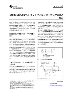
2 Encoder Interpolation ElectronicsAServo DriveEncoder Phase ADDDDBZS tatusRRRRE ncoder Phase BEncoder IndexStatusMotion ControllerDS26LV31 TDS26LV32AT MARCH 1999 REVISED JULY 2020 Copyright 2020 Texas Instruments IncorporatedSubmit Document Feedback1 Product Folder Links: DS26LV31 TDS26LV31 TJAJS868D MARCH 1999 REVISED JULY 2020 TI TI English Data Sheet: SNLS114 Table of Contents1.
3 12 ..13 ..14 Revision Pin Configuration and Absolute Maximum ESD Recommended Operating Thermal Resistance Electrical Switching Characteristics - Industrial Switching Characteristics - Military DS26LV31W .. Typical Parameter Measurement Detailed Functional Block Feature Device Functional Application and Application Typical Power Supply Layout Layout Device and Documentation Documentation Receiving Notification of Documentation Support Electrostatic Discharge Mechanical, Packaging, and Revision History Changes from Revision C (February 2013) to Revision D (June 2020)Page.
4 1 ESD ..1 Changes from Revision B (March 1999) to Revision C (February 2013)Page TI ..1DS26LV31 TJAJS868D MARCH 1999 REVISED JULY Document FeedbackCopyright 2020 Texas Instruments IncorporatedProduct Folder Links: DS26LV31T5 Pin Configuration and Functions D1 D4 D2 D3(16) VCC(15) DI 4(14) DO 4+(13) DO 4-(12) EN*(11) DO 3-(10) DO 3+(9) DI 3Di 1 (1)DO 1+ (2)DO 1- (3)EN (4)DO 2- (5)DO 2+ (6)DI 2 (7)GND (8) 5-1.
5 Dual-In- line Package (Top View)Pin FunctionsPINI/O(1) 11 IDriver 1 inputDO 1+2 ODriver 1 outputDO 1-3 ODriver 1 inverted outputEN4 IActive high enableDO 2-5 ODriver 2 inverted outputDO 2+6 ODriver 2 outputDI 27 IDriver 2 inputGND8 GGround pinDI 39 IDirver 3 inputDO 3+10 ODriver 3 outputDO 3-11 ODriver 3 inverted outputEN*12 IActive low enableDO 4-13 ODriver 4 inverted outputDO 4+14 ODriver 4 outputDI 415 IDriver 4 inputVCC16 PPower pin(1) I = Input, O = Output, I/O = Input or Output, G = Ground, P = MARCH 1999 REVISED JULY 2020 Copyright 2020 Texas Instruments IncorporatedSubmit Document Feedback3 Product Folder Links: DS26LV31T6 Specificationsover operating free-air temperature range (unless otherwise noted)(1) (2) Absolute Maximum RatingsMINMAXUNITVCCS upply Voltage , EN*Enable Input Voltage + Input Voltage + Diode Current 2020mADC Output Current, per pin 150150mADriver Output Voltage(Power Off.)
6 DO+, DO ) temperature 65150 C(1) Stresses beyond those listed under absolute maximum ratings may cause permanent damage to the device. These are stress ratingsonly and functional operation of the device at these or any other conditions beyond those indicated under recommended operatingconditions is not implied. Exposure to absolute-maximum-rated conditions for extended periods may affect device reliability.(2) If Military/Aerospace specified devices are required, please contact the TI Sales Office/Distributors for availability and ESD RatingsVALUEUNITV (ESD)Electrostatic dischargeHuman-body model (HBM), per ANSI/ESDA/JEDECJS-001(1)Driver output pins 7000 VOther pins 2500(1) JEDEC document JEP155 states that 500-V HBM allows safe manufacturing with a standard ESD control operating free-air temperature range (unless otherwise noted)
7 Recommended Operating ConditionsMINNOMMAXUNITVCCS upply Free Air Temperature RangeDS26LV31T 402585 CDS26LV31W 5525125 CInput Rise and Fall Thermal Resistance CharacteristicsTHERMAL METRIC(1)DS26LV31 TUNITSOIC (D)16 PinsR JAJunction-to-ambient thermal C/WR JBJunction-to-board thermal C/WR JCJunction-to-board thermal C/W JTJunction-to-top characterization C/W JBJunction-to-board characterization C/WR JC(bot)Junction-to-case (bottom) thermal resistancen/a C/W(1) For more information about traditional and new thermal metrics, see the Semiconductor and IC package thermal metrics MARCH 1999 REVISED JULY Document FeedbackCopyright 2020 Texas Instruments IncorporatedProduct Folder Links.
8 DS26LV31 Tover operating free-air temperature range (unless otherwise noted)(1) (2) Electrical CharacteristicsPARAMETERTEST CONDITIONSPinMINTYPMAXUNITVOD1 Output differential VoltageRL = (No Load)DO+,DO differential VoltageRL = 100 ( 7-1),IO 20 VOD2 Change in Magnitude of OutputDifferential Voltage 4007400mVVOD3 Output differential VoltageRL = 3900 ( ) 7-1 and (3) Mode VoltageRL = 100 ( 7-1 ) VOCC hange in Magnitude ofCommon Mode Voltage 4006400mVIOZTRI-STATE Leakage CurrentVOUT = VCC or GND Drivers Disabled 20 AISCO utput Short Circuit CurrentVOUT = 0 VVIN = VCC or GND (4)TA = 40 C to+85 C 40 70 150mATA = 55 C to+125 C (5)
9 30 160mAIOFFO utput Leakage CurrentVCC = 0 V, VOUT = 3 V or 6 AVCC = 0 V,VOUT = VTA = 40 C to+85 C 100 ATA = 55 C to+125 C 200 AVIHHigh Level Input VoltageDI, EN,EN*2 VCCVVILLow Level Input Level Input CurrentVIN = VCC10 AIILLow Level Input CurrentVIN = GND 10 AVCLI nput Clamp VoltageIIN = 18 mA Supply CurrentNo Load,VIN (all) = VCC orGNDTA = 40 C to+85 CVCC100 ATA = 55 C to+125 C125 A(1) Current into device pins is defined as positive. Current out of device pins is defined as negative. All voltages are referenced to groundexcept differential voltages VOD1, VOD2, VOD3.
10 (2) All typicals are given for VCC = + V, TA = +25 C.(3) This specification limit is for compliance with TIA/EIA-422-B and ITU-T (4) Only one output shorted at a time. The output (true or complement) is configured High.(5) This parameter does not meet the TIA/EIA-422-B MARCH 1999 REVISED JULY 2020 Copyright 2020 Texas Instruments IncorporatedSubmit Document Feedback5 Product Folder Links: DS26LV31 Tover operating free-air temperature range (unless otherwise noted)(1) (2) Switching Characteristics - Industrial DS26LV31 TPARAMETERTEST CONDITIONSMINTYPMAXUNITtPHLDD ifferential Propagation Delay Highto LowRL = 100 , CL = 50 pF( 7-2 and 7-3) Propagation Delay Lowto High61116nstSKDD ifferential Skew (same channel) |tPHLD tPLHD| , Pin to Pin (same device)12nstSK2 Skew, Part to Part (3)35nstTLHD ifferential Transition Time Low toHigh (20% to 80%) Transition Time High toLow (80% to 20%) Time High to Z( 7-4 and 7-5)