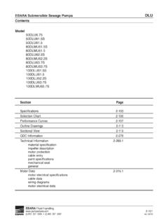
Transcription of EBARA Submersible Sewage Pumps DLFU Contents
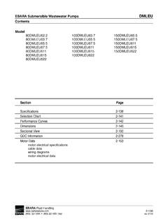
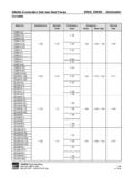
1 EBARA Submersible Sewage PumpsDLFUC ontentsProject:Model:Chk d:Date:Model 100 DLFU611100 DLMFU611100 DLFU615100 DLMFU615 Chart2-165 Performance Curves2-166 Outline Drawings2-191 Sectional View2-210 QDC Information2-278 Technical specificationimpeller descriptionmotor protectioncable entrypaint specificationsmechanical sealgeneralMotor electrical specificationscable datawiring diagramsmotor electrical dataEBARAF luid (t) 803 327 5005 (f) 803 327 5097 rev. 11/02 EBARA Submersible Sewage PumpsDLFUC ontentsProject:Model:Chk d:Date:EBARAF luid (t) 803 327 5005 (f) 803 327 5097 rev. 01/02 EBARA Submersible Sewage PumpsDLFUM odel DesignationProject:Model:Chk d:Date:DISCHARGE SIZE mm50mm 2" 200mm 8"80mm 3" 250mm 10"100mm 4" 300mm 12"150mm 6"MODEL TYPEDLF/DLMF Submersible Sewage pumpDLFM/DLMFM FM explosion proof designationGEOGRAPHIC DESIGNATIONU marketHERTZ6 - 60 RATED 10HP22 3HP11 15HP30 5HP15 20HP37 71/2HP18 25HP45 60 HPPHASE none three phaseVOLTAGE2 - 208/2304 - 4605 - 575100 (t) 803 327 5005 (f) 803 327 5097 rev.
2 01/02 EBARA Submersible Sewage PumpsDLFUS pecificationsProject:Model:Chk d:Date:Model DLFUS pecificationsStandardOptionalSize2, 3, 4, 6, 8, 10, 12 inchRange of HP2 to 60 HPRange of PerformanceCapacity 13 to 4000 GPMHead 7 to 243 feetLimitationMaximum Water Temperature104 F (40 C)Synchronous Speed1800 RPMM aterialsCasingCast IronImpellerCast Iron (2 to 60HP)Ductile Iron (150-300 DLFU 40 to 60 HP)Shaft403 Stainless Steel (2 to 5HP)420 Stainless Steel (71/2to 60HP)Motor FrameCast IronFastener304 Stainless SteelMechanical SealDouble Mechanical SealMaterial Upper SideCarbon/Ceramic (2 to 60HP)Tungsten Carbide/Tungsten CarbideMaterial Lower SideSilicon Carbide/Silicon Carbide (2 to 60HP)Tungsten Carbide/Tungsten CarbideTungsten Carbide/Tungsten Carbide (150-300 DLFU50 and 60HP only)Impeller TypeSemi-open (2 to 30HP)Enclosed (40 to 60HP)
3 BearingPrelubricated Ball BearingMotorInsulation Class F (2-5HP), H (71/2to 60HP) FM Explosion Proof, Class 1, Three Phase208/230/460 VDivision 1, Group C, DService ProtectionThermal Detector KlixonsMechanical Seal Leakage Detector Float SwitchSubmersible cable 33 ft. (2 to 5HP)____ ft. (customer specified)50 ft. (71/2to 60HP)AccessoriesQDC SystemEBARAF luid (t) 803 327 5005 (f) 803 327 5097 rev. 02/13 EBARA Submersible Sewage PumpsDLFUS pecificationsProject:Model:Chk d:Date:EBARAF luid (t) 803 327 5005 (f) 803 327 5097 rev. 10/11A. General:Provide Submersible Sewage Pumps suitable for continuous duty operation underwater without loss of watertight integrity to a depth of 65 feet. Pump system design shall include a guide rail system be such that the pump will be automatically connected to the discharge piping when lowered into place on the discharge connection.
4 The pump shall be easily removable for inspection or service, requiring no bolts, nuts, or other fasteners to be disconnected, or the need for personnel to enter the wet well. The motor and pump shall be designed, manufactured, and assembled by the same Manufacturer: EBARA International CorporationC. Pump Characteristics: Pumps shall conform to the following requirements:Number of unitsDesign flow (gpm)Design TDH (ft)Minimum shut off head (ft)RPM1800 Maximum HPMinimum efficiency at design (%)Minimum power factor at design (%)Voltage/HZ208/230V, 460V / 60 Phase3D. Pump Construction:All major parts of the pumping unit(s) including casing, impeller, suction cover, wear rings, motor frame and dischargeelbow shall be manufactured from gray cast iron, ASTM A-48 Class 30.
5 Castings shall have smooth surfaces devoid of blow holes or other casting irregularities. Casing design shall be centerline discharge with a large radius on the cut water to prevent clogging. Units shall be furnished with a discharge elbow and 125 lb. flat face ANSI flange. All exposed bolts and nuts shall be 304 stainless steel. All mating surfaces of major components shall be machined and fitted with NBR o-rings where watertight sealing is required. Machining and fitting shall be such that sealing is accomplished by automatic compression of o-rings in two planes and o-ring contact is made on four surfaces without the requirement of specific torque limits. Internal and external surfaces are prepared to SPPC-VISI-SP-3-63 then coated with a zinc-chromate primer.
6 The external surfaces are then coated with a Teneme-Tar 46H-413 Polyamide Epoxy - Coal Tar paint1. Impellers:a. For units 2 to 5 HP, the impeller shall be radial single or multi-vane, semi-open design. It shall be dynamically balanced and shall be designed for solids handling with a long thrulet without acute turns. The inlet edge of the impeller vanes shall be angled toward the impeller periphery so as to facilitate the release of objects that might otherwise clog the pump. The 2 to 5 HP impeller design shall also include back pump out vanes to reduce the pressure and entry of foreign materials into the mechanical seal area. In addition, a lip seal shall be located behind the impeller hub to further reduce the entry of foreign materials into the seal area.
7 Impellers shall be direct connected to the motor shaft with a slip fit, key driven, and secured with an impeller bolt. The design shall include a replaceable cast iron suction cover. The suction cover shall be designed such that it may be adjusted to maintainworking clearances and hydraulic For units 71/2to 30 HP, the impeller shall be a mixed flow multi-vane semi-open design. It shall be dynamically balanced and shall be designed for solids handling with a long thrulet without acute turns. The inlet edge of the impeller vanes shall be angled toward the impeller periphery so as to facilitate the release of objects that might otherwise clog the pump. The 71/2to 30 HP impeller design shall also include back pump out vanes to reduce the pressure and entry of foreign materials into the mechanical seal area.
8 In addition, a lip seal shall be located behind the impeller hub to further reduce the entry of foreign materials into the seal area. Impellers shall be direct EBARA Submersible Sewage PumpsDLFUS pecificationsProject:Model:Chk d:Date:EBARAF luid (t) 803 327 5005 (f) 803 327 5097 rev. 10/11connected to the motor shaft with a slip fit, key driven, and secured with an impeller bolt. The design shall include a replaceable cast iron suction cover. The suction cover shall be designed such that it may be adjusted to maintain working clearances and hydraulic For high head units with 4'' discharge, 40 to 60 HP shall have a radial multi-vane, enclosed impeller design. It shall be dynamically balanced and shall be designed for solids handling with a long thrulet without acute turns.
9 The inlet edge of the impeller vanes shall be angled toward the impeller periphery so as to facilitate the release of objects that might otherwise clog the pump. A lip seal shall be located behind the impeller hub to reduce the entry of foreign materials into the mechanical seal area. Impellers shall be direct connected to the motor shaft with a slip fit, key driven, and secured with an impeller bolt. The design shall include a replaceable casing wear ring at the pump suction to maintain working clearances and hydraulic For units 6'' to 12'' discharge sizes, 40 to 60 HP, the impeller shall be a mixed flow multi-vane enclosed design. It shall be dynamically balanced and shall be designed for solids handling with a long thrulet without acute turns. The inlet edge of the impeller vanes shall be angled toward the impeller periphery so as to facilitate the release of objects that might otherwise clog the pump.
10 A lip seal shall be located behind the impeller hub to reduce the entry of foreign materials into the seal area. Impellers shall be direct connected to the motor shaft with a slip fit, key driven, and secured with an impeller bolt. The design shall include a replaceable casing wear ring at the pump suction to maintain working clearances and hydraulic K-series design:e. For units 2 to 5 HP, the impeller shall be radial single or multi-vane, semi-open design. It shall be dynamically balanced and shall be designed for solids handling with a long thrulet without acute turns. The inlet edge of the impeller vanes shall be angled toward the impeller periphery so as to facilitate the release of objects that might otherwise clog the pump. The 2 to 5 HP impeller design shall also include back pump out vanes to reduce the pressure and entry of foreign materials into the mechanical seal area.