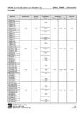
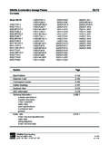
Transcription of EBARA Submersible Sewage Pumps DLU
1 EBARA Submersible Sewage PumpsDLUC ontentsProject:Model:Chk d:Date:Model Chart2-106 Performance Curves2-107 Outline Drawings2-113 Sectional View2-119 QDC Information2-278 Technical specificationimpeller descriptionmotor protectioncable entrypaint specificationsmechanical sealgeneralMotor electrical specificationscable datawiring diagramsmotor electrical dataEBARAF luid (t) 803 327 5005 (f) 803 327 5097 rev. 02/15 EBARA Submersible Sewage PumpsDLUM odel DesignationProject:Model:Chk d:Date:DISCHARGE SIZE mm50mm 2"80mm 3"100mm 4"MODEL TYPEDL Submersible Sewage pumpGEOGRAPHIC DESIGNATIONU marketHERTZ6 - 60 RATED 5 HPPHASES single phasenone three phaseVOLTAGE2 - 208/2304 - (t) 803 327 5005 (f) 803 327 5097 rev.
2 01/02 EBARA Submersible Sewage PumpsDLUS pecificationsProject:Model:Chk d:Date:Model DLUS pecificationsStandardOptionalSize2, 3, 4 inchRange of HP1 to 2 HP Three Phase1 to 5 HP Single PhaseRange of PerformanceCapacity 13 to 430 GPMHead 9 to 66 feetLimitationMaximum Water Temperature 104 F (40 C)Synchronous Speed1800 RPMM aterialsCasingCast IronImpellerCast IronShaft403 Stainless SteelMotor FrameCast IronFastener304 Stainless SteelMechanical SealDouble Mechanical SealMaterial Upper SideCarbon/CeramicMaterial Lower SideSilicon Carbide/Silicon Carbide Impeller TypeSemi-openBearingPrelubricated Ball BearingMotorAir-filled, Insulation Class FSingle Phase208/230 VThree Phase208/230/460 VService ProtectionSingle PhaseBuilt-in Auto Cut - overload, out of phase, single Three Phasephasing protectionAccessoriesSubmersible cable 33 SystemEBARAF luid (t) 803 327 5005 (f) 803 327 5097 rev.
3 01/02 EBARA Submersible Sewage PumpsDLUS pecificationsProject:Model:Chk d:Date:A. General:Provide Submersible Sewage Pumps suitable for continuous duty operation underwater without loss of watertight integrity to a depth of 65 feet. If mounted on a guide rail system, design shall be such that the pump will be auto-matically connected to the discharge piping when lowered into place on the discharge connection. The pump shall be easily removable for inspection or service, requiring no bolts, nuts, or other fasteners to be disconnected, or the need for personnel to enter the wet well. The motor and pump shall be designed, manufactured, and assembled by the same Manufacturer: EBARA International CorporationC.
4 Pump Characteristics: Pumps shall conform to the following requirements:Number of unitsDesign flow (gpm)Design TDH (ft)Minimum shut off head (ft)RPM1800 Maximum HPMinimum efficiency at design (%)Minimum power factor at design (%)Voltage/HZ208/230V, 460V / 60 PhaseImpeller shall be single vane semi-open design for 1-2 HP units, single or multi-vane semi-open design for 3 HP units, and multi-vane semi-open design for 5 HP units. The impeller design shall include back pump out vanes to reduce the pressure and entry of foreign materials into the mechanical seal area. The inlet edge of the impeller vanes shall be angled toward the impeller periphery so as to facilitate the release of objects that might otherwise clog the pump.
5 Impellers shall be direct connected to the motor shaft with a slip fit, key driven, and secured with an impeller bolt. The unit shall include a replaceable suction cover that is designed such that it may be adjusted to maintain working clearances and hydraulic mechanical seals operating in an oil bath shall be provided on all units. The oil filled seal chamber shall be designed to prevent over-filling and include an anti-vortexing vane to insure proper lubrication of both seal faces. Lower face materials shall be silicon carbide vs. silicon carbide, upper faces carbon vs. ceramic, NBR elastomers, and 304SS hardware. Seal system shall not rely on pumping medium for (t) 803 327 5005 (f) 803 327 5097 rev.
6 01/02D. Pump Construction:All major parts of the pumping unit(s) including casing, impeller, suction cover, motor frame and discharge elbow shallbe manufactured from gray cast iron, ASTM A-48 Class 30. Castings shall have smooth surfaces devoid of blow holes or other casting irregularities. Casing design shall be centerline discharge with a large radius on the cut water to prevent clogging. Units shall be furnished with a discharge elbow and 125 lb. flat face ANSI flange. All exposed bolts and nuts shall be 304 stainless steel. All mating surfaces of major components shall be machined and fitted with NBR O-rings where watertight sealing is required. Machining and fitting shall be such that sealing is accomplishedby automatic compression of O-rings in two planes and O-ring contact is made on four surfaces without the requirementof specific torque limits.
7 Internal and external surfaces are prepared to SSPC-VIS1-3-63 then coated with a zinc-rich epoxy primer. The external surfaces are then coated with a Tneme-Tar 46-413 coal tar Submersible Sewage PumpsDLUS pecificationsProject:Model:Chk d:Date:E. Motor Construction:The pump motor shall be an air filled induction type with a squirrel cage rotor, shell type design, built to NEMA MG-1, Design B specifications. Stator windings shall be copper, insulated with moisture resistant Class F insulation, rated for 311 F. The stator shall be dipped and baked three times in Class F varnish and heat shrunk fitted into the stator housing. Rotor bars and short circuit rings shall be manufactured of cast aluminum.
8 Motor shaft shall be one piece AISI403 material, rotating on two permanently lubricated ball bearings designed for a minimum B-10 life of 60,000 hours. Motor service factor shall be and capable of up to 20 starts per hour. The motor shall be designed for continuous duty pumping at a maximum sump temperature of 104 F. Voltage and frequency tolerances shall be a maximum 10 / 5% respectively. Junction area shall include a terminal board for power connections on all three (3) phase units. Motor protection shall be provided by an auto-cut device located directly over the windings to provide protection from single phasing, low voltage, phase imbalance, locked rotor, and no load or run dry shall be non-overloading over the entire performance curve and be able to operate at full load intermittently while unsubmerged without damage to the cable jacket shall be manufactured of an oil resistant chloroprene rubber material, designed for submerged applications.
9 Cable shall be watertight to a depth of a least 65'. Cable entry shall be composed of a one piece, vulcanized, three way mechanical sealing system with a thick molded shoulder with increasing cable diameters to resist fatigue from bending forces. The molded shoulder, acts as the primary and secondary sealing points. This system shall also prevent leakage into the motor housing due to capillary action through the insulation if the cable is damaged or cut. A metallic plate shall be utilized to clamp the entry system to the motor housing. Strain relief shall be accomplished by clamping and attaching the cable with chain to the motor housing. F. Guide Rail system:Design shall include two (2) 304SS schedule 40 guide rails sized to mount directly to the quick discharge connector, QDC, at the floor of the wet well and to a guide rail bracket at the top of the wetwell below the hatch opening, (refer to project drawings).
10 Intermediate guide brackets are recommended for rail lengths over 15 rails are not part of the pump package and shall be supplied by QDC shall be manufactured of cast iron, ASTM A48 Class 30. It shall be designed to adequately support the guide rails, discharge piping, and pumping unit under both static and dynamic loading conditions with support legs that are suitable for anchoring it to the wetwell floor. The face of the inlet QDC flange shall be perpendicular to the floor of the wetwell. The discharge flange of the QDC shall conform to ANSI Class pump design shall include an integral self-aligning sliding bracket. Sealing of the pumping unit to the QDC shall be accomplished by a single, linear, downward motion of the pump.