Transcription of ECEN 607 (ESS)
1 1 BandgapReference: BasicsThanks for the help provided by M. Mobarak ,Faramarz Bahmani and Heng ZhangECEN 607 (ESS)2 Outline Introduction Temperature-independent reference PTAT generator Supply insensitive current source Design example 3 Introduction Conditions to be satisfied for an IC in production: Work even when Vcc changes (Supply variation): eg: Vcc: Work even when temperature changes (Temperature variation): eg: T: -25C 0 25C 75C Work even when physical properties change (Process variation): BJTs: : 30% MOS: : 10%, Vth: 100mV Resistors: R: 20% Capacitors: C: 5% Inductors: L: 1% All combinations of supply voltage (Vcc), temperature (T) and process (P) variations have to be considered in design. This is often referred to as PVT (process, voltage and temperature)4 Introduction: Case studySmall signal gain variation with PVT: Supply variation: low frequency gain almost insensitive to VCCvariation (assuming Q in active region) Temperature variation: gm is changing (decreasing) with T (assuming ICQindependent of T) gain is dependent on temperature.
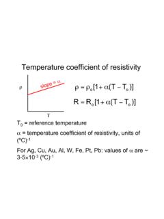
2 Solution: Make ICQa function of T (increases with T) gain remains insensitive to T. Process variations: In BJTs, VT=KT/q is almost insensitive to process variation (assuming ICQinsensitive to process variations) gm remained intact. However, variations in resistor R results in gain variation. VccRRQ1Q2biasI+Vin Vin ====qKTICQTCQ mminoutVIgRgVVGain5 Introduction: Case studySmall signal gain variation with PVT: Supply variation: low frequency gain almost insensitive to VCCvariation (assuming Q in active region) Temperature and Process variations: Holding R/Rs constant low frequency gain is held constant. can be easily accomplished by using the same type of resistors for R & Rs following the standard layout practices to achieve good component matching Bad news: The gain has significantly reduced!VccbiasIRQ1+VinRQ1+VinRsRsRsRVVG aininout =6 Temperature-Independent Referenceref1212 VVV=cc0TT T += ref1122 VcVcV=+ Reference voltages and/or currents with little dependence to temperature prove useful in many analog circuits.
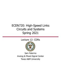
3 Key idea: add two quantities with opposite temperature coefficient with proper weighting the resultant quantity exhibits zero temperature coefficient . Eg: V1 and V2 have opposite temperature dependence, choose the coefficients c1 and c2 in such a way that: Thus, the reference voltage Vrefexhibits zero temperature : NTCTif c , c0V0: PTCT < > > 7 Bandgap Voltage Reference Target: A fixed dc reference voltage that does not change with temperature. Useful in circuits that require a stable reference voltage. ADC The characteristics of BJT have proven the most well-defined quantities providing positive and negative TC kT/q has a positive temperature coefficient "PTAT" proportional to absolute temperature VBE of a BJT decreases with temperature "CTAT" complementary to absolute temperature Can combine PTAT + CTAT to yield an approximately zero TC voltage reference8 Thermal behavior of BJTQBEQVCQICBESIKTVln()qI=expBECSTVIIV = Even though KT/q increases with temperature, VBEdecreasesbecause ISitself strongly depends on temperature I0is a device parameter, which also depends on temperature We'll ignore this for now VG0is the bandgap voltage of silicon "extrapolated to 0 K"Assuming both I0and ICare constant over T.
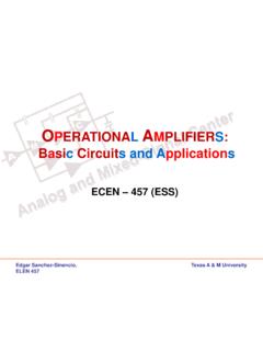
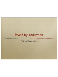
4 9 Extrapolated Bandgap[Pierret, AdvancedSemiconductorFundamentals, ]10 PTAT Generator Amplifying the difference in VBEof two BJTs PTAT term Different VBEvoltages can be obtained by: Applying different ICQ Using two BJT s with different emitter areas but equal ICQQ2ccVCQ2 IBE2VQ1ccVCQ1 IBE1V0T V1II if)IIln(qKTV-VVBECQ2CQ1CQ2CQ1BE2BE1BE> >== CQCQBEQ1 BEQ2 IIKTKTVln() , Vln()q Aq mA==ln(m)qKTV-VVBEQ2 BEQ1 BEQ== 11 Bandgap Voltage Reference Generate an inverse PTAT and a PTAT and sum them appropriately. VBEis inverse PTAT at roughly mV/ C at room temperature Vt= kT/q is PTAT that has a temperature coefficient of + mV/ C at room temperature. Multiply Vtby a constant M and summed with the VBEto get VREF= VBE+ MVt12 Bandgap Voltage ReferenceCombining VBEand an appropriately scaled version of kT/qproduces a temperature independent voltage, equal to VG013 PTAT GeneratortR1R1112R22 R1t1R221 VVIln(m)RR2RV2 RIVln(m)RV2 RKln(m)0 ; PTC!
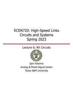
5 TRq==== => How do we generate a voltage that is the difference of two VBE?CQCQBE1BE2 IIKTKTVln() , Vln()q Aq mA==1 BEBE1BE2 KTVV-Vln(m)qRV= ==IR1IR1+-VR114 Bandgap Voltage Reference More to come!R2BE1 BGVVV+=(NTC) 0 TVBE1< (PTC) 0 TVR2> 15 Supply Insensitive Current Source How can we generate the bias currents ICQ? Conventional current mirror: Current is essentially proportional to VDD if VDDvaries by X%, bias current will roughly vary by the same amount. Supply insensitive current source:By using a sufficiently large device,we can make VOV<< Vt, and achieve:16 Supply Insensitive Current Source In the above discussed bias generator circuits, the supply sensitivity is still fairly high, because IINis essentially directly proportional to VDD Idea: Mirror output current back to input instead of using supply dependent input current!
6 17 Start-up CircuitThere exists a stable operating point with all currents =0(weak)Can use a simple start-up circuit to solve this problem18 PTAT Current Generation19 Compatibility with CMOS Technology In CMOS technologies, where the independent bipolar transistors are not available, parasitic bipolar transistors are used. Realization of PTAT voltage from the difference of the source-gate voltages of two MOS transistors biased in weak inversion is also reported in the literature."parasitic" substrate PNP transistor available in any CMOS technology20 CMOS Bandgap Reference With Substrate PNP BJTs21 Design example()223ln1outBETRVV VnR =++ Specifications:Vsupply: 5V, CMOS processVref : dependence: < 60ppm/CXY1 2EQ2EQ12223131232222233223VV, RR, AA1; ; ln( )ln( )1ln()CoutEBRRCREBEB EBTRRRToutEBTnJVV VVJnVV V VVnVRVRIRVnRRRVVVnR== = = =++= = === = = ++ A critical point: DC output of Op Amp should be > 700mV for start up22 Choice of n Usually make n=integer2-1, n=8 Layout:23 Simulations Result24A Low-Supply-Voltage CMOS Sub-Bandgap ReferenceRef: A.
7 Becker-Gomez, T. L. Viswanathan, Viswanathan, "A Low-Supply-Voltage CMOS Sub-Bandgap Reference," IEEE Transactions on Circuits and Systems II: Express Briefs, , , , July 2008 Low supply voltage No resistor or op-amp is used, thus it is compatible with digital processes25A Low-Supply-Voltage CMOS Sub-Bandgap Reference() = =()2i2 PTATiSG2SG1 PTAT/nA1kVII/nkAI/kVVV = = =PTATBE2iiPTATBE2 BGiSG2SG6BE2 BGVm/rV/nA1/nAm/rVVVI/nkAmI/rkVVVV+ += = = r is the ratio between M6/M1 m is the ratio between M5/M1 For Ai<<1, n>>126 SummaryHow to Build a Generate two currents and dump into the transistors2. Add a mechanism to force Vo1= Vo23. Add a scale factor to generate zero TC output4. Startup circuit, some tweakingDone!!!27 References First bandgap voltage reference:R. J. Widlar, "New developments in IC voltage regulators," IEEE J.
8 Solid-State Circuits, pp. 2-7, Feb. 1971. A classic implementation:A. P. Brokaw, "A simple three-terminal IC bandgapreference, IEEE J. Solid-State Circuits, pp. 388-393, Dec. 1974. Design of Analog Integrated Circuits, Behzad Razavi Analysis and Design of Analog Integrated Circuits, Gray, P. Hurst