Transcription of Measuring Temperature with Thermocouples – a Tutorial
1 Application Note 043. Measuring Temperature with Thermocouples a Tutorial Travis Ferguson Introduction One of the most frequently used Temperature transducers is the thermocouple. Thermocouples are very rugged and inexpensive and can operate over a wide Temperature range. A thermocouple is created whenever two dissimilar metals touch and the contact point produces a small open-circuit voltage as a function of Temperature . This thermoelectric voltage is known as the Seebeck voltage, named after Thomas Seebeck, who discovered it in 1821.
2 The voltage is nonlinear with respect to Temperature . However, for small changes in Temperature , the voltage is approximately linear, or V S T (1). where V is the change in voltage, S is the Seebeck coefficient, and T is the change in Temperature . S varies with changes in Temperature , however, causing the output voltages of Thermocouples to be nonlinear over their operating ranges. Several types of Thermocouples are available; these Thermocouples are designated by capital letters that indicate their composition according to American National Standards Institute (ANSI) conventions.
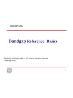
3 For example, a J-type thermocouple has one iron conductor and one constantan (a copper-nickel alloy) conductor. You can monitor Thermocouples with versatile PC-based data acquisition systems. Thermocouples have some special signal conditioning requirements, which this note describes. The Signal Conditioning eXtensions for Instrumentation (SCXI) system, depicted in Figure 1, is a signal conditioning front end for measurement devices. SCXI systems are ideal for amplifying, filtering, and even isolating the very low-level voltages that Thermocouples generate.
4 D an ls s is f i edigna h as i pl d S. X IC Am lat e SC Is o SCX. I-10. 01. SCXI. 1140. SCXI. 1140. SCXI. 1140. SCXI. 1140. SCXI. 1140. SCXI. 1140. SCXI. 1140. SCXI. 1140. SCX SCXI. MAINF. I 1140. RAME. SCXI. 1140. SCXI. XI. 1140. SCdule M o XIal SCXI. ta n SC. 1140. m r s in Daisitio Telock q ice u B AcDev SCX. I. 1100. d anrs n alsuce g d Sians d Tr re y s fermor an e Tr M. a tatly to Drec Di Figure 1. The SCXI Signal Conditioning Front-End System for Plug-In DAQ Devices LabVIEW , Measurement Studio , NI-DAQ , , and National Instruments are trademarks of National Instruments Corporation.
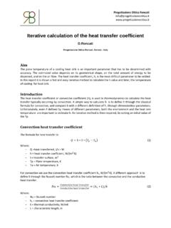
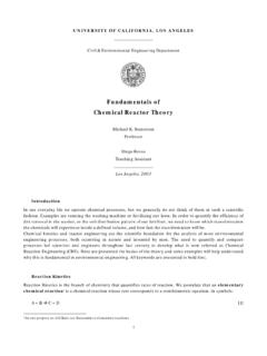
5 Product and company names mentioned herein are trademarks or trade names of their respective companies. 340524D-01 Copyright 2001 National Instruments Corporation. All rights reserved. February 2001. J3 (+). ,,,,,,,,,,,,,, ,,,,,,,,,,,,,, ,,,,,,,,,,,,,, To DAQ Board J2 ( ) J1. ,,,,,,,,,,,,,, ,, Constantan ,, ,, ,, Iron Copper Figure 2. J-Type Thermocouple Thermocouple Circuits General Case To measure a thermocouple Seebeck voltage, you cannot simply connect the thermocouple to a voltmeter or other measurement system, because connecting the thermocouple wires to the measurement system creates additional thermoelectric circuits.
6 Consider the circuit illustrated in Figure 2, in which a J-type thermocouple is in a candle flame that has a Temperature you want to measure. The two thermocouple wires are connected to the copper leads of a DAQ board. Notice that the circuit contains three dissimilar metal junctions J1, J2, and J3. J1, the thermocouple junction, generates a Seebeck voltage proportional to the Temperature of the candle flame. J2 and J3 each have their own Seebeck coefficient and generate their own thermoelectric voltage proportional to the Temperature at the DAQ terminals.
7 To determine the voltage contribution from J1, you need to know the temperatures of junctions J2 and J3 as well as the voltage-to- Temperature relationships for these junctions. You can then subtract the contributions of the parasitic Thermocouples at J2 and J3 from the measured voltage. Cold-Junction Compensation Thermocouples require some form of Temperature reference to compensate for these unwanted parasitic Thermocouples . The term cold junction comes from the traditional practice of holding this reference junction at 0 C.
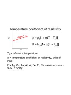
8 In an ice bath. The National Institute of Standards and Technology (NIST) thermocouple reference tables are created with this setup, illustrated in Figure 3. Application Note 043 2 ,,,,,,,,,,,,,, +. ,,,,,,,,,,,,,, ,,,,,,,,, T. Voltmeter ,,,,,,,,,,,,,, ,,,,,,,,, 1. ,,, ,,, ,,,,,,,,, ,,, ,,,,,,,,, . ,,, ,,,,,,,,, Isothermal Region Ice Bath Tref = 0 C. ,, Metal 1. Copper ,, ,, ,, Metal 2. Figure 3. Traditional Temperature Measurement with Reference Junction Held at 0 C. In Figure 3, the measured voltage depends on the difference in temperatures T1 and Tref; in this case, Tref is 0 C.
9 Notice that because the voltmeter lead connections are the same Temperature , or isothermal (this term is described in detail later in this note), the voltages generated at these two points are equal and opposing. Therefore, the net voltage error added by these connections is zero. Under these conditions, if the measurement Temperature is above 0 C, a thermocouple has a positive output; if below 0 C, the output is negative. When the reference junction and the measurement junction are the same Temperature , the net voltage is zero.
10 Although an ice bath reference is accurate, it is not always practical. A more practical approach is to measure the Temperature of the reference junction with a direct-reading Temperature sensor and subtract the parasitic thermocouple thermoelectric voltage contributions. This process is called cold-junction compensation. You can simplify computing cold-junction compensation by taking advantage of some thermocouple characteristics. By using the Thermocouple Law of Intermediate Metals and making some simple assumptions, you can see that the voltage the DAQ board measures in Figure 2 depends only on the thermocouple type, the thermocouple voltage, and the cold-junction Temperature .