Transcription of ECT-DIN Datasheet Feb 2016 - Moore Industries …
1 Signal Isolator, Converter, Repeater, Booster and SplitterECT-DIN 2016 Moore Industries -International, 2016 Featuring metal DIN-style housings, the ECT snaps securely onto standard G-type and Top Hat Current and voltage inputs. Available models handle Current and Voltage Signals. 2-wire (loop) and 4-wire (line/mains) powered. Versatile choices allow you to match the ECT to the type of AC or DC power available at each location. Superior signal isolation (up to 1500 Vrms). Industrial-strength protection stops ground loops, motor noise, and other electrical interferences from affecting process signals. RFI/EMI protection. The ECT provides an effective barrier against the unpredictable, harmful effects of radio frequency and electromagnetic interference.
2 When ordered with the -RF option, the ECT delivers enhanced protection for especially noisy 1To choose the right ECT for your application, fi rstdetermine the power supply characteristics:Underwriter s Laboratories: Ordinary(non-hazardous) or Hazardous Locations*Class I, Division 2, Groups A, B, C & D T4CE: Conformant to EMC Directive 2014/30/EU EN 61326; Low Voltage Directive 2014/35/EU EN 61010*Certifi cation not applicable to ECT-DIN models equipped with the-RF option or 4-wire, line/mains powered, dual input cations ListedCUSD escriptionECT DIN-style signal isolators, converters, repeaters, boosters and splitters feature solid metal housings that stand up to the continuous, daily rigors of process control and factory automation applications.
3 Rugged and reliable, the ECT is available in 2-wire (loop) and 4-wire (line/mains) powered models. The complete family delivers economical solutions for an expansive range of signal interface applications. Isolate Signals to stop erratic measurements caused by ground loops. Convert Signals so fi eld instruments can interface directly with an indicator, recorder, DCS, PLC or PC-based SCADA system. Split One Signal to allow one primary measurement to be sent to two separate systems. Get two isolators in one. The ECT is available in dual channel I/O models that provide application fl exibility while reducing space requirements and costs. Protect Equipment and Signals (Area Isolation) by eliminating common electrical paths.
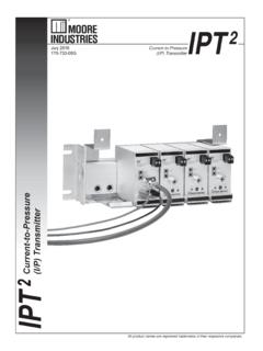
4 Amplify (Boost) Signals so that more instruments can be added to an overburdened loop. Solve Bucking Power Supplies by stopping a confl ict caused by a 4-wire transmitter and a DCS both trying to power the same process loop. Step Down Dangerous, high voltage signals to safer levels to protect plant personnel. Solve DCS Start-Up Problems caused by non-isolated transmitters by installing an ECT in each troublesome loop. Power Supply Type Page2-Wire, Output-Loop Powered 2-3(12-42 Vdc)2-Wire, Input-Loop Powered 4-5( )4-Wire, Line/Mains Powered 6-7(117 Vac, 230 Vac, 24 Vdc)206-710-09 LSignal Isolator, Converter, Repeater, Booster and SplitterECT-DINPage 22-Wire, Output-Loop Powered ModelsThis ECT model derives operating power from its output side where loop power is typically made available by the receiving device, such as a DCS.
5 Stop Ground Loop NoiseDifferences in potential between a grounded transmitter and a grounded receiving device may result in unpredictable ground loop problems, which can lead to signal drift. Use the ECT to break the galvanic path between the fi eld instrument and receiving device (Figure 1).Convert SignalsThe ECT takes one process signal type (such as 1-5V) and converts it to a standard, isolated 4-20mA, allowing devices with incompatible signal types to interface with one another (Figure 1).Divert and Protect (Area Isolation) SignalsUsing the ECT, you can send the output from one transmitter to a second location; protect expensive monitoring/control equipment by eliminating common electrical paths; or create a buffer between devices to allow interruption of one leg of a loop without impacting the other (Figure 2).
6 Amplify (Boost) SignalsIf you need to add an instrument to an overloaded loop, use the ECT. It features a high drive capability of 600 ohms (with a 24V power supply) and a low input impedance of just 50 ohms (Figure 3).Solve Bucking Power SuppliesWhen two devices (such as a 4-wire transmitter and a DCS) are trying to source power to the same loop, the result is a non-functioning loop. When neither of the devices can be eliminated, the solution is a 2-wire ECT. It can operate with powered inputs from both sides, thus restoring normal operations to the loop (Figure 4).Figure 1. Input/output loop isolation and signal XMITTERPLC opto isolationDCSI solated4-20mA LoopECTI solated4-20mA Loop+ +++ PS+ PS Figure 2.
7 Divert a process signal, or protect expensive equipment by eliminating a common electrical XMITTERPID(250 ohms)opto isolationDCSINTEGRATOR(250 ohms)(into 600 ohmsmaximum)4-20mAECT4-20mAinto 600 ohms +++++ PS+ PS Figure 3. Boost process signals to allow another instrument to be added to an otherwise overloaded XMITTERDCS opto isolationECT24V24V PS +++ PS+Figure 4. Restore a loop experiencing bucking power supplies to normal TRANSMITTERRECEIVERNON-ISOLATED4-WIRETRA NSMITTERRECEIVERRECEIVER++ +24V+ +IN1-5 VOUTPUT LOOPPOWEREDI solated4-20mAopto isolationECTS ignal Isolator, Converter, Repeater, Booster and SplitterECT-DINPage 3 Specifi cationsFigure 5. To protect plant personnel, step down potentially dangerous high level AC current signals to lower level Input Overrange: Current Inputs 250% of full scale; DC Voltage Inputs, 150% of full scaleBurden: 1V maximum with 4-20mA input; maximum with 0-5A inputLoad Capability: Output Current Limiting: 25mA typical; 30mA maximumOperating Range: -40 C to +85 C(-40 F to +185 F)Storage Range: -40 C to +85 C(-40 F to +185 F)Ordering InformationECT2-wire (Output-Loop Powered) Isolator/Converter4-20MA into 50 ohms1-5V into 1 Mohm0-10V into 1 Mohm0-150AC into 100 kohms0-5 AAC into ohms4-20MA into 600 ohms with 24 Vdc power supply4-20 MAB* See bi-directional note below12-42DC-DI Differential input.
8 Performs A-B subtraction of two inputs where input A will always be larger than input B. The 4-20mA output will equal 0-100% difference between A and B inputs*-EM Externally-mounted input transformer for current input (available with 0-5 Aac input type only)-RF Enhanced RFI/EMI fi ltering provides 30V/m @ 20-1000 MHz protection with less than of span error-VTD Standard Factory Calibration with NIST Test Data ReportDIN Aluminum DIN-style housing mounts on 32mm G-type (EN50035) and 35mm Top Hat (EN50022) railsFLB2 Externally-mounted fl ange provides a secure mount and ensures resistance to vibrationPerformancePerformance(continue d)When ordering, specify: Unit / Input / Output / Power / Options [Housing] Model number example.
9 ECT / 4-20MA / 4-20MA / 12-42DC / -RF [DIN]AmbientConditionsAmbientConditions( Continued)WeightAdjustmentsStep Down Unsafe High Level Signals To protect plant personnel, the ECT comes with an optional external input transformer (-EM option) to step down high level AC current inputs to a low level signal. This permits safer servicing without opening the secondary of a current transformer (Figure 5).RECEIVER+opto isolationPOWERSUPPLY PS ++PSISOLATED4-20mAECTE xternally MountedCurrent Transformer(-EM option)0-5 AACCT/PT0-5mACT/PTAmbient TemperatureEffect: of span/ C typical; of span/ C maximumRelative Humidity:0-95% non-condensingRFI/EMI Protection: Less than of span error when tested at 10V/m@ 20-1000 MHz WITH -RF OPTION: Less than of span error when tested at 30V/m@ 20-1000 MHz Common Mode Rejection:Exceeds 95dB@60Hz with a limit of 1500 VrmsType: Front panel potsSpan: 10%Zero: 5%(non-interactive when span is set fi rst)145g (5 oz)Vs - *If input A is not always larger than input B, the ECT will provide a bi-directional 4-20mA output.
10 The 4-20mA output will be 12mA when A=B, 20mA when input A is 100% and input B is 0%, and 4mA when input B is 100% and input A is 0%. In this case the output designation in the model number should be identifi ed as 4-20mAB, denoting bi-directional : of span ( for 0-150 AC inputs)Stability: of reading per yearIsolation: WITHOUT -RF OPTION: 1500 Vrms between input and output; WITH -RF OPTION: 500 Vrms between input and output Output Response Time: DC Inputs, 100msec to 99% of output maximum; AC Inputs, 400msec to 99% of output Ripple: 10mV peak-to-peak maximum measured across a 250 ohm resistorOver-Voltage Protection: 48V, maximum on output; 48V reverse polarity protection on outputSignal Isolator, Converter, Repeater, Booster and SplitterECT-DIN2-Wire, Input-Loop Powered ModelsThe 2-wire, input-loop powered ECT derives its operating power from the input side of the process loop (Figure 6).