Transcription of (EECtechnical.doc .. 11.20.97) Technical Notes on …
1 111/20/97( .. ) Technical Notes on The EEC-IV MCUC ompiled by Tom Cloud (all fonts are Courier New)(The information supplied here was gotten through researching e-mail correspondence, Technical publications and from information given to the author. If it helps you, great!If you learn more about the EEC, please return the favor by sharing what you learn withme and others.)If you were a contributor and didn't get acknowledged, flame me and I'll get it right inthe "next" edition. There were many contributors who didn't want me to remember them, soI chose to delete most original corresponcences, hence the high probability that I mayhave failed to acknowledge someone who wanted to be given : Beware -- none of this data is guaranteed to be accurate! Use it at yourown risk and please let me know what you learn so that I can add to and correct :INTRODUCTIONTHE MCU/ECUTHE MICROPROCESSORCPU, ROM, RAM PINOUT8061 MEMORY MAP8061 INSTRUCTION SETMCU PARTS LISTECM TEST PORT (J3) PINOUTECM CABLE PINOUTEEC DIAGNOSTICSEEC FUEL CONTROLEEC IGNITION and TIMING CONTROLEEC FUNCTIONSEEC SCALARSEEC TABLESMAF CONVERSIONTERMSEEC APPLICATIONSEEC-IV REFERENCE SOURCESAFTERMARKET SUPPLIERSINTRODUCTIONI've collected and compiled data to help you decipher the EEC-IV inner algorithms and automotive control techniques are purposely absent astheEEC hardware and chip set are what I'm primarily interested in figuring EEC MCU probably controls one or more vehicles you own plus it contains allthe components necessary to build an efi system for any vehicle -- if only wecould program and modify it.
2 That is my purpose -- to uncloak the EEC-IV sothat we can play with what we bought!The sections titled EEC DIAGNOSTICS, FUEL CONTROL, IGNITION & TIMING CONTROL,FUNCTIONS, SCALARS AND TABLES are departures from the goals stated above -- butI felt it was informative and hated to discard it. If this were a formaldocument, I would probably either ditch those sections, re-structure thedocument's purpose to include them or write a separate document on MCUThe EEC-IV was introduced in 1983 and has gone through several major physicalchanges, with the earliest models showing a fairly simple two board design usingthrough hole soldered components. The last of the EEC-IV designs were much morecurrent in technology, showing extensive use of surface mount components and amuch more finished and complex appearance. In between, there appears to be avariety of mother/daughter board and other designs. Still, they are all calledEEC-IV, although somewhere in its life there was a Ford P/N generational writes: "The processor used is the 8065 alongwith several supporting peripheral chips like the DUCE chip which can provide upto 8 PWM outputs and the DARC chip which has 6 channels of timer captureinputs.
3 " (Is he talking about the EEC-V here ?)"This control unit is more suited to a history class than modern enginemanagement systems. All of the functions within the EEC, apart from the actualpower drivers, are now found within the micro controller such as the 68332 and336."The EEC module is rated to 80C (185F) continuous, 100C intermittent, so it willbe much happier and live longer in the passenger compartment. Some of the latergeneration 15 and 18 MHz Motorola 8061 processors have a bus loading/edge timingsensitivity that only gets worse at high temperature, so it's best to keep theEEC in a more hospitable environment. Additionally, mounting the EEC in thepassenger compartment will give you better access to the J3 test port, which iswhere you'll be plugging in a chip and/or the J3 test port on the side of the ECU box is for developers to plug into --this is how the after-market chipmakers and others get into the box. The testconnector has the micro-controller's multiplexed address/data bus signals on also, very conveniently, has a PROM disable signal.
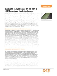
4 So the chip makersdesign something that hangs off that connector, disables the computer's PROM,and substitutes its own PROM in its MICROPROCESSOR:The micro-controller is an Intel 8061, a close cousin to the Intel 8096. It issupplied by three manufacturers: Intel, Toshiba (6127) and Motorola, though theMotorola unitsseem to slip speca little anddiffer in theirtiming slightlyfrom the are somemajor differencesbetween the 8061and 8096 ( , buslayout, etc.),but most of thecode 8061 is an8096 with a fewextrainstructionsadded. One is avery powerfulconditional jumpto complement thehigh speed I/Ounits. Thisinstruction, thejump on bit equals zero, is used to test any one of the eight bits of a givenbyte and jump if the bit equals zero (is this the JBC/JNB command?). Otherconditional jumps were added to aviod extensive data shifts. With a 15 MHzinput frequency, the 8061 can perform a 16-bit addition in microseconds anda 16 x 16 bitmultiply or a 32/16bit divide in (usingthe hardwaremultiply and dividefeature).
5 Fortypicalapplications, basedon a normalinstruction mix,instructionexecution timesaverage 1 to 2microseconds. Itseems to have thesame functional pinsas the 8096, butit's in a custompackage, so thepinout is of the signalsshould be able to befound with a scopeor logic 8096 has aREAD-ONLYMEMORY(16K X 16)CIRCUITS8763 EPROMREADONLYPORT BO UU FT FDATACONTROLSIGNALSMBUSMB0-MB7 ADDRESSMUXDATAOUT BI UN F FDATAADDRESSREGISTERSLAVEPROGRAM COUNTERMACHINESTATE LOGIC881616 ADDRENABLERP0RP5I/O88 TRI-STATECONTROL PROCESSORINSTRUCTIONREGISTERXTALI/OCIRCU ITSINTERRUPTCONTROLLER,WATCHDOGTIMER, I/OSTATUSREGISTER8061 MICROPROCESSORCTRL&I/OINTERFACEHI SPEEDINPUTSANALOGINPUTSBIDIRECTI/O 6HI SPEEDOUTPUTSLO SPEEDOUTPUTSRALUPROGRAMCOUNTERREGISTERFI LE(120 X 16)STACKPOINTERM BB UU FS FBUFFADDR DATADATA DATADATAD-BUS (16)DATAADDR/DATAADDR8 LSBsADDR A-BUS 8 OPCODEMBUSMB0-MB7411/20/97 RANDOM-ACCESSMEMORY(1K X 16)CIRCUITS81C61 RAM - I/OI/OPORT BO UU FT FDATACONTROLSIGNALSMBUSMB0-MB7 ADDRESSOUTMUXDATA BI UN F FDATAADDRESSREGISTERSLAVEPROGRAM COUNTERMACHINESTATE LOGIC51616 ADDR/DATAENABLEI/O-0I/O-4I/O88 TRI-STATEDATAINASSYEXECUTEENABLEREGISTER 16858 DATA multiplexed address/data bus.
6 The address/data bus signals are on the serviceport connector (J3) along with a few others, possibly including the addresslatch enable, read strobe, write strobe, and EPROM are atleast twohardware versionsof the 8061 is a 40 pinDIP and the otheris a square LCC68 pin 68 pinversion has moreI/O and perhapsother scheme issimilar to thatof the 8085 whichhas AD0 .. AD7and then A8 ..A15 so the 8085"latches" theaddressinformation A7:0,and maintainsA8:15 while it isusing AD0 .. AD7as D7:0 ..On the 8061 there are ONLY AD0 .. AD7 none of the "other" address lines so ..when the 8061 wants to read an address it must1) present 8 bits of the address and send the latch signal2) present the OTHER 8 bits of the address and send the latch3) enable the "Read Enable" flag, and read the 8 data bitsLEGENDADDR ADDRESS I/O INPUT/OUTPUTASSY ASSEMBLY LO LOWA-BUS ADDRESS BUS LSB LEAST SIGNIFICANT BITBIDIRECT BIDIRECTIONAL MBus MEMORY BUSBUFF BUFFER EPROM ERASABLE READ-ONLY MEMORYCTRL CONTROL MUX MULTIPLEXERD-BUS DATA BUS RAM RANDOM ACCESS MEMORYHI HIGH RPn READ-ONLY PORT INPUTCPU, ROM, RAM PINOUT8061 CPU (IC-1)
7 1 35 GND2 36 Vss+337438539511/20/9764074184294310 44 MB011 Vcc 45 MB112 46 MB213 47 MB314 48 MB415 49 MB516 50 MB617 51 MB718 GND 5219 5320 TP analog in 5421 5522 5623 5724 5825 5926 6027 6128 6229 6330 6431 6532 MAP f-v 66 xtal33 67 xtal34 6887C61 RAM/IO (IC-7)1 13 CPU-65, J3-13 MB32 /OE 14 CPU-64, J3-11 MB43 15 CPU-63, J3-9 MB54 GND (?)
8 16 CPU-62, J3-7 MB65 17 CPU-61, J3-5 MB76 GND (?) 187 19 GND (?)8 20 address bit9 21 address bit10 CPU-68, J3-19 MB0 22 address bit11 CPU-67, J3-17 MB1 2312 CPU-66, J3-15 MB2 24 GNDCPU is IC-1, J3 is service connector8763 EPROM (IC-8)1 J3-22, 1K to +5V 13 CPU-65, J3-13 MB32 J3-16, 10K to +5 14 CPU-64, J3-11 MB43 15 CPU-63, J3-9 MB54 GND 16 CPU-62, J3-7 MB65 17 CPU-61, J3-5 MB76 18 +5V7 +5 19 +5V8 GND 20 CPU-59, J3-219 J3-12 21 CPU-58, J3-23611/20/9710 CPU-68, J3-19 MB0 22 CPU-57, J3-2511 CPU-67, J3-17 MB1 2312 CPU-66, J3-15 MB2 24 GNDCPU is IC-1, J3 is service connector[As far as the memory chips go on the ram chip pins 4, 6, 19, 24 all connectedto GND, and 3, 5, 7 all went to VRef (Dan S.)]
9 ]8061 MEMORY MAP(This memory map came from a difficult to readpicture. The things I'm unsure of are: The "REG" at 00. Anything with "?" in it. The number of "?" shows the number of characters Ithink are there. The OA00H address at the beginning of the KAM area. The Interrupt Vector addresses: 2010H - 201FH. The D000H/E000H address at the beginning of the Engineering Console (40K)INTERRUPT VECTORS2010H - 201 FHENGINEERINGCONSOLE (4K)CALIBRATIONCONSOLE (4K)KAM (???)FUTURE USE (???)EXTERNAL RAM (????)INTERNALREGISTERS(???)STACK TIME TIME0D BUFFER COMMAND0C MASK MASK0B DATA NOT USED0A I/O STATUS I/O STATUS09 INT. PEND INT. PEND08 INT. MASK INT. MASK0706 TIMER NOT USED05 A/D HI WATCHDOG04 A/D LO A/D COMMAND03 I/O PORT I/O PORT02 PORT PORT0100 ZERO REG NOT USEDREAD WRITEThe 8061 uses the same address space for program and for data memoryand can execute instructions from any memory address.)
10 Its addressingrange is 64k locations and the first 256 locations are on-chip and refer tothe internal register file. All other memory resides INSTRUCTION SET===================================== ======================================== Summary, 8096 instructions vs. 8061 instructions============================ ======================================== ========= 32 instructions the same 43 instructions the same, but renamed 8 instructions the same, but split into 2 pseudo-ops (2 vs. 3 operands) 7 instructions in 8061, not in 8096 -- bank0/1/2/3 -- retei -- rombank -- signd 6 instructions in 8096, not in 8061 -- br -- divu/divub -- mulu/mulub -- rst===================================== ======================================== Instructions in 8096 alphabetical orderop-code 8096 8061 description difference============================== ======================================== =======64-67 add ad2w add words (2 operands) -- split44-47 " ad3w add words (3 operands) -- split74-77 addb ad2b add bytes (2 operands) -- split54-57 " ad3b add bytes (3 operands)