Transcription of Efficient Pneumatic Conveying Dense Phase vs. Dilute Phase ...
1 Efficient Pneumatic Conveying Dense Phase vs. Dilute Phase : How Being Accurate is More Cost Effective Than Being Conservative Kody W. Smajstrla, LB Industrial Systems, San Antonio TX KEYWORDS: Dense Phase , Dilute Phase , Pneumatic , Conveying , Fly Ash Submitted for consideration in the 2013 World of Coal Ash Conference, April 22-25, 2013. INTRODUCTION In the coal combustion products realm there is a growing trend towards requiring Dilute Phase Pneumatic Conveying as a rule. The first hurdle to meet with this mindset is to actually define Dilute Phase . A widely accepted definition available for Dilute Phase flow is a two Phase flow where all of the conveyed particles are carried in suspension [1].
2 From a practical standpoint this definition is useless as, short of installing sections of transparent pipe, there is no way to verify whether 100% of the conveyed material is being carried in suspension. The next logical step is to determine some measurable properties to serve as the delineation between Dense and Dilute Phase . Commonly gas velocities and pressure drops are selected to serve this purpose. The problem with such a definition is that for it to hold true for a range of materials, the values need to be very conservative. For example, it is not unusual to hear a plant engineer or operator state that a pressure Conveying system that operates with air velocities over 3000 ft/min or overall pressure drops of less than about 15 psi is indeed a Dilute Phase system.
3 The question you should be asking yourself is Is this cost effective? PROBLEM From the viewpoint of a design and supply firm overly conservative design requirements are wonderful. At such elevated airflow rates one needs little to no knowledge of the material. At 3000+ ft/min one could successfully convey iron powder through a pipeline so fly ash with its characteristic permeability, air retention, and ease of Conveying can certainly be moved with little concern [2]. So now I can cut costs by not having to invest in the expertise of my design engineers. To meet the higher velocities I also get to supply much larger blowers than may be necessary; another increase in profit margin. To keep the pressure 2013 World of Coal Ash (WOCA) Conference - April 22-25, 2013 in Lexington, within range at these elevated specified velocities larger pipe is usually necessary.
4 Now I am providing more pounds of steel per foot of conveyance thanks to increased pipe sizes and beefier supports required to keep it all in the air. As pipeline erosion is a function of airflow proportional to the range of velocity squared to velocity cubed, a dramatically increased erosion rate at and near fittings should be expected [3]. Again, as a design and supply firm I see dollar signs. Now I can provide hardened fittings, hardened pipe, and severe service valves. The beauty of these components is, although they will slow the erosion rate, they do not stop the actual damage mechanism. So they WILL wear out and if I can convince the client that they need MY proprietary fittings and valves they will have to come back to me to purchase the replacements.
5 This aspect can be so lucrative that I may be willing to actually sacrifice profit on the initial project just to get my foot in the door and enrich myself as a parts provider. It should be obvious that blindly setting such conservative limits stacks the deck in the design and supply firm s favor. As the customer who is spending hundreds of thousands, if not millions, of dollars on such products shouldn t you be provided with a system that is designed with efficiency and reliability ( , your best interest) in mind? STUDY This study examines a recent proposal where the customer requested a system to be designed to a conservative Dilute Phase specification. The system was designed and quoted per the customer specification; however, an alternative system design was quoted for comparison by the customer applying a hybrid Phase approach tailored to the customer s performance requirements.
6 The following paragraphs will describe the system layout, design method, final design differences, and financial differences. CUSTOMER SPEC INTERNAL SPEC Pressure Conveying Overall Pressure Drop Requirement Less than 15 psi Within the capabilities of a commonly available blower or compressor. Pressure Conveying Minimum Air Velocity 3,000 ft/min 2,000 ft/min (Considered conservative without the benefit of a full scale material analysis) Vacuum Conveying Overall Pressure Drop Requirement Must fall within the capabilities of a commonly available vacuum blower Must fall within the capabilities of a commonly available vacuum blower Vacuum Conveying Minimum Air Velocity 3,500 ft/min 2,500 ft/min (Considered conservative without the benefit of a full scale material analysis) TABLE 1: DESIGN SPECIFICATIONS SYSTEM DESCRIPTION The system proposed is a combination vacuum and pressure Conveying system.
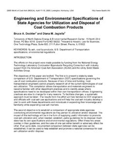
7 Figure 1 shows the plan view of the equipment locations and pipe routing. The target Conveying rate is 34 tons of fly ash per hour. The vacuum Conveying system begins at the base of the unit baghouse where the ash/air mixture is pulled by vacuum from the baghouse hoppers into the collector, which feeds an airlock discharging into the transfer tank. See Appendix A for flow diagram. The pipe route includes 316 feet of horizontal pipe, 67 feet of vertical pipe, and eight 90 degree elbows. The transfer tank fills the transfer vessels where the pressure Conveying system takes over and compressed air is used to push the ash/air mixture to the storage silo. See Appendix B for flow diagram. The pressure Conveying route consists of 3108 feet of horizontal pipe, 130 feet of vertical pipe, and eight 90 degree elbows.
8 FIGURE 1: Plan View of Piping Route DESIGN OVERVIEW A critical parameter of a Pneumatic Conveying system design is the minimum pickup velocity of the material [4]. This is the minimum air velocity at which an aerated material will join the air flow [5]. It is the critical nature of this parameter that influences many designers to be overly conservative in its definition. Material testing is the best way to get a definitive range for this parameter. For preliminary design purposes previous material testing of a very similar material can be used with the addition of a reasonable safety factor until testing of actual system material can be performed. The minimum pickup velocity is determined as part of the material lab testing.
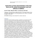
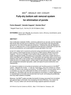
9 Sample material is conveyed through the system detailed in Figure 2: Lab Conveying Loop Schematic. FIGURE 2: LAB Conveying LOOP SCHEMATIC The material is conveyed through the system in a series of runs at varying rates of material feed and transfer air supply while taking pressure readings at the various locations as indicated in Figure 2. After completion, a chart is assembled plotting pressure drop values with respect to air and material flow rates (See Figure 3). FIGURE 3: ISO-PRESSURE LINES FROM RAW DATA REGRESSION From here the lab scale procedure detailed by David Mills (Mills 2004, Mills 2009) is utilized to scale the material/air flows and pressure drops from the relatively small lab system to the final full scale system design.
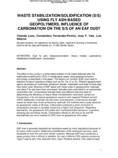
10 It is not the intention of this study to present this method in detail. However, in summary, the method relies on two well proven assumptions which are logically and iteratively applied. The first assumption is that for two piping segments of equal diameter, equal air mass flow rates, and equal pressure drop attributed to material flow the ratio of the material mass flow rates equals the ratio of their lengths (See Figure 4). The second assumption is that for two piping segments of equal solids loading ratios (mass flow rate of material divided by mass flow rate of air) and equal average velocities the pressure drop attributed to material flow rate will be equal per unit length (See Figure 4). ASSUMPTION #1 System A System B IF: and BaAamm,, =BpApPP,, = THEN: AeBeBpApLLmm,,,,= ASSUMPTION #2 System A System B PER UNIT LENGTH L BASLRSLR= and BiAiCC,,= IF: THEN: = = LPLPBpAp,,Constant FIGURE 4: LAB SCALE PROCEDURE ASSUMPTIONS The result of the procedure is a series of graphs similar to Figure 5 from which a pressure drop of a piping segment can be determined at a multitude of combinations of air and material flow rates.