Transcription of EGR 1098H EGR Pressure Reducing Regulators Instruction …
1 W6956 Figure 1. Type 1098-EGRT ypes 1098-EGR and 1098H -EGR Pressure Reducing Regulators WARNINGF ailure to follow these instructions or to properly install and maintain this equipment could result in an explosion, fire and/or chemical contamination causing property damage and personal injury or Regulators must be installed, operated and maintained in accordance with federal, state and local codes, rules and regulations and Emerson Process Management Regulator Technologies, Inc. (Emerson) the regulator vents gas or a leak develops in the system, service to the unit may be required. Failure to correct trouble could result in a hazardous condition. Installation, operation and maintenance procedures performed by unqualified personnel may result in improper adjustment and unsafe operation. Either condition may result in equipment damage or personal injury. Use qualified personnel when installing, operating and maintaining the Types 1098-EGR and 1098H -EGR Pressure Reducing of the ManualThis manual describes and provides instructions and parts list for Type 1098-EGR or 1098H -EGR regulator complete with a standard P590 Series filter and either a 6350 Series regulator, a 61 Series pilot or a Type Y600AM pilot.
2 The Type 1806 check valve is also covered when a 61 Series pilot is used. instructions and parts lists for monitoring pilots and other equipment used with this regulator are found in separate 1098-EGR and 1098H -EGR Regulators provide economical and accurate Pressure control in a wide variety of applications: natural gas distribution systems; fuel gas supply to industrial boilers, furnaces, ovens and mixers; and large commercial/industrial establishments such as shopping centers and schools. They are also used in plant air service and in liquid 2020 Types 1098-EGR and 1098H -EGRI nstruction ManualD100339X012 SpecificationsThe Specifications section lists Pressure limitations and other specifications for various Types 1098-EGR and 1098H -EGR constructions. Specifications for a given regulator as it originally comes from the factory are stamped on nameplates located on both the actuator and main valve body, while the pilot control spring range is displayed on the pilot spring case and the pilot restriction code is stamped on the pilot body (S = standard gain, L = low gain and H = high gain).
3 To determine maximum Pressure ratings, the individual ratings for the main valve, actuator and pilot must all be Sizes and End Connection StylesSee Table 1 Main Valve Maximum Inlet Pressure (1)400 psig / bar or body rating limit whichever is lowerMaximum Pilot Supply Pressure (1)(2)600 psig / barOutlet Pressure RangesSee Table 2 Actuator Sizes and Maximum PressuresSee Table 3 Maximum and Minimum Differential PressuresSee Table 4 Main Valve Flow CharacteristicLinear (standard), Whisper Trim or Quick openingMain Valve Flow DirectionIn through the seat ring and out through the cagePressure RegistrationExternalProcess Temperature Capabilities(1)(3)Nitrile (NBR): -20 to 180 F / -29 to 82 CFluorocarbon (FKM): 0 to 300 F / -18 to 149 C, Water is limited to 0 to 200 F / -18 to 93 CEthylenepropylene (EPDM): -20 to 275 F / -29 to 135 COptions NACE Construction Boiler Fuel Construction Aqueous Service Construction Monitor Configuration Noise Abatement Trim1.
4 The Pressure /temperature limits in this Instruction Manual or any applicable standard limitation should not be For stability or overpressure protection, a Reducing regulator may be installed upstream of the pilot according to the Installation Special low temperature constructions for process temperatures between -76 F / -60 C to 185 F / 85 C are available by request. The low temperature construction passed Emerson laboratory testing for lockup and external leakage down to -76 F / -60 1. Body Sizes and End Connection StylesBODY SIZECAST IRONSTEEL OR STAINLESS STEELNPSDN1 or 2 25 or 50 NPT or CL125 FFNPT, CL150 RF, CL300 RF, CL600 RF, BWE, SWE or PN 16/25/403, 4 or 6 80, 100 or 150CL125 FFCL150 RF, CL300 RF, CL600 RF, BWE or PN 16/25/408 x 6 or 12 x 6200 x 150 or 300 x 150- - - -CL150 RF, CL300 RF, CL600 RF or BWET ypes 1098-EGR and 1098H -EGR2 Table 2. Outlet Pressure RangesPILOT TYPEOUTLET Pressure RANGESPRING COLORSPRING PART NUMBER psigbar63513 to 20 5 to 35 35 to 100 to to to GreenUnpaintedRed1B9860272121B7883270221 K748527202635214 in.
5 To 2 psig 2 to 10 35 mbar to bar to YellowBlack14A9672X01214A9673X01263533 to 40 35 to 125 to to YellowRed1E3925270221K7485272026354L(1)8 5 to to Blue1L3461271426354M(2)175 to to Blue1L3461271426354H(2)200 to to Green15A9258X01261L61LD61LE7 in. to 2 psig1 to 5 2 to 10 5 to 15 10 to 20 17 mbar to to to to to Red YellowBlueBrownGreen1B8863270221J8578270 221B8864270221J8579271421B88652702261H10 to 65 to Green Stripe0Y06642702261HP15 to 45 35 to 100 100 to 300 to to to YellowBlueRed1E3925270221D3872270221D465 127142Y600AM4 to 8 in. 7 to 16 in. 15 in. to to to to 7 10 to 20 mbar17 to 40 mbar37 mbar to bar to to to RedUnpaintedYellowGreenLight BlueBlack1B6538270521B6539270221B5370270 521B5371270221B5372270221B5373270521. Without diaphragm With diaphragm 3. Actuator Sizes and Maximum PressuresACTUATOR TYPEACTUATOR SIZEOUTLET CONTROL PRESSUREEMERGENCY CASING Pressure psigbarpsigbar10983040 (standard)7010075 50 4.
6 Maximum and Minimum Differential Pressures for Main Valve SelectionBODY SIZESPRING PART NUMBERSPRING COLORMAXIMUM ALLOWABLE DIFFERENTIAL Pressure (1) MINIMUM DIFFERENTIAL Pressure REQUIRED FOR FULL STROKESize 30 ActuatorSize 40 ActuatorSize 70 ActuatorNPSDN psigbarpsigbarpsigbarpsigbar1 2514A9687X012 Green60 Blue125 Red400(3) (3)7 5014A6768X012 Yellow20 - - -- - - Green60 Blue125 Red400(3) (3)11 8014A6771X012 Yellow20 - - -- - - Green60 4 Blue125 Red400(3) (3)14 10014A6770X012 Yellow20 - - -- - - Green60 Blue125 Red400(3) (3)22 , 8 x 6 or 12 x 6 150, 200 x 150 or 300 x 15015A2253X012 Yellow20 - - -- - - Green60 Blue125 Red400(3) (3)28(2) (2)19 Maximum inlet Pressure is equal to set Pressure plus maximum Requires special 6300 Series pilot construction without integral check valve and with external Type 1806H 40 psid / bar d check Should not exceed the body rating limit.
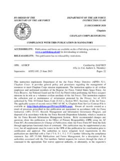
7 Use this Pressure value or the body rating limit, whichever is 1098-EGR and 1098H -EGR3 Table 5. Recommended Type MR95H Pressure Settings for Use with the Type Y600AM PilotBODY SIZETYPE EGRSPRING COLORSUPPLY PRESSUREType Y600AM Spring ColorRedUnpaintedYellowGreenLight BlueBlackNPSDN psigbarpsigbarpsigbarpsigbarpsigbarpsigb ar1 or 8 x 6 150 or 200 x The pressures shown in the table are the minimum supply pressures required by the pilot. If the inlet Pressure is less than shown, an external pilot supply is of OperationThe pilot-operated Types 1098-EGR and 1098H -EGR Regulators both use inlet Pressure as the operating medium, which is reduced through pilot operation to load the actuator diaphragm. Outlet or downstream Pressure opposes loading Pressure in the actuator and also opposes the pilot control spring. The Type 1098- EGR regulator operation schematic is shown in Figure operation, assume that outlet Pressure is below the pilot control setting.
8 Control spring force on the pilot diaphragm opens the pilot valve plug providing additional loading Pressure to the actuator diaphragm. This loading Pressure forces the actuator stem forward, opening the main valve plug via a bump connection. The upward motion of the plug allows gas to flow through the cage into the downstream downstream demand has been satisfied, outlet Pressure tends to increase, acting on the pilot and actuator diaphragms. This Pressure exceeds the pilot control spring setting, moving the pilot diaphragm away and letting the valve plug spring (Type 6351, 61 Series or Type Y600AM pilots) or bellows (Types 6352 through 6354M pilots) close the pilot valve plug (unbalanced in the Type 6351 or 61 Series pilots but balanced in the Types 6352 through 6354M pilots). Excess loading Pressure on the actuator diaphragm escapes downstream through the bleed hole (Type 6351 pilot), bleed orifice (61 Series pilot), restriction (Types 6352 through 6354M pilots) or fixed restrictor (Type Y600AM pilot).
9 Reduced actuator loading Pressure permits the main valve to close. The combination of main valve spring force and valve plug imbalance provides positive valve plug shutoff against the port and upper protect the Type 1098 or 1098H actuator diaphragm from excessive differential Pressure , the 6350 Series pilots have an integral check valve that allows loading Pressure to bleed downstream at approximately 25 psig / bar differential across the actuator diaphragm. An external check valve (Type 1806) is required when the required minimum differential is higher than 25 psi / bar or when using the 61 Series or Y600AM pilots with the normal operation of the 1098-EGR and 1098H -EGR4A6563A6641 TYPE 1098-EGR WITH TYPE 61LD PILOTTYPE 1098-EGR WITH 6350 SERIES PILOTINLET PRESSUREOUTLET PRESSUREATMOSPHERIC PRESSURELOADING PRESSUREINLET PRESSUREOUTLET PRESSUREATMOSPHERIC PRESSURELOADING PRESSURETYPE 6351 TYPE 1098-EGRTYPE 6352,6353 OR 6354 TYPE 1098-EGRTYPE 1806 TYPE 61 LDFigure 2.
10 Operational SchematicsTypes 1098-EGR and 1098H -EGR5 TYPE MR95 HTYPE 1098-EGRTYPE Y600 AMOPTIONAL:TYPE 112 RESTRICTORFIXED RESTRICTORTYPE 1098-EGR WITH TYPE Y600AM PILOT AND TYPE MR95H Pressure SUPPLY REGULATORINLET PRESSUREOUTLET PRESSUREATMOSPHERIC PRESSURELOADING PRESSUREPILOT SUPPLY PRESSUREF igure 2. Operational Schematics (continued)M1008 Installation and Startup WARNINGP ersonal injury, equipment damage or leakage due to escaping accumulated gas or bursting of Pressure -containing parts may result if this regulator is overpressured or is installed where service conditions could exceed the limits given in the Specifications section and on the appropriate nameplate or where conditions exceed any ratings of the adjacent piping or piping connections. To avoid such injury or damage, provide Pressure -relieving or Pressure -limiting devices to prevent service conditions from exceeding those , physical damage to the regulator may result in personal injury and property damage due to escaping accumulated gas.