Transcription of EJX510A, EJX530A Absolute and Gauge Pressure Transmitters
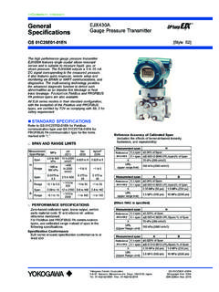
1 <<Contents>> <<Index>>. General EJX510A and EJX530A . Specifications Absolute and Gauge Pressure Transmitter GS 01C25F01-01EN [Style: S2]. The high performance Absolute and Gauge Pressure transmitter EJX510A and EJX530A feature single crystal silicon resonant sensor and are suitable to measure liquid, gas, or steam Pressure . EJX510A. and EJX530A output a 4 to 20 mA DC signal corresponding to the measured Pressure . It also features quick response, remote setup and monitoring via BRAIN or HART communications, diagnostics, and optional status output for Pressure high/low alarm. The multisensing technology provides the advanced diagnostic function to detect such abnormalities as an impulse line blockage or heat trace breakage.
2 FOUNDATION Fieldbus and PROFIBUS PA protocol types are also available. All EJX series models in their standard configuration, with the exception of the Fieldbus and PROFIBUS. types, are certified as complying with SIL 2 for safety requirement. Reference Accuracy of Calibrated Span STANDARD SPECIFICATIONS (includes the effects of terminal-based linearity, Refer to GS 01C25T02-01EN for Fieldbus hysteresis, and repeatability). communication type and GS 01C25T04-01EN for PROFIBUS PA communication type for the items Measurement Reference Accuracy marked with . span Span X Span<X. A ( URL/ span)% of Span SPAN AND RANGE LIMITS. B ( + URL/ span)%.
3 (For EJX510A, values are in Absolute Pressure C of Span of Span and lower range limits are 0.). D ( URL/ span)% of Span Measurement psi bar kgf/cm2. MPa Span/Range (/D1) (/D3) (/D4) Measurement A B C D. 8 to 200 span Span to 29 to 2 to 2. kPa 20 kPa MPa 1 MPa 5 MPa A X. 100 to to ( psi) (29 psi) (145 psi) (720 psi). Range 1 to 2 1 to 2. 200 kPa 29 URL 200 kPa 2 MPa 10 MPa 50 MPa Span to 2 to 290 to 20 to 20 (Upper range limit) (29 psi) (290 psi) (1450 psi) (7200 psi). B to Range to 2 1 to 20 1 to 20. 290 Ambient Temperature Effects per 28 C (50 F). Span to 10 29 to 1450 2 to 100 2 to 100 Change C to ( of Span + of URL). Range to 10 1 to 100 1 to 100.
4 1450 Stability (All normal operating condition). 145 to EJX530A : of URL for 15 years Span 1 to 50 10 to 500 10 to 500. 7200 EJX510A: of URL for 15 years D. to Power supply Effects Range to 50 1 to 500 1 to 500. 7200 % per Volt (from to 32 V DC, 350 ). Vibration Effects PERFORMANCE SPECIFICATIONS Amplifier housing code 1 and 3: Zero-based calibrated span, linear output, wetted Less than of URL when tested per the parts material code S' and silicone oil, unless requirements of IEC60770-1 field or pipeline otherwise mentioned. with high vibration level (10-60 Hz, mm For Fieldbus and PROFIBUS PA communication displacement/60-2000 Hz 3 g).
5 Types, use calibrated range instead of span in the Amplifier housing code 2: following specifications. Less than of URL when tested per the Specification Conformance requirements of IEC60770-1 field with general EJX series ensures specification conformance to at application or pipeline with low vibration level (10-60. least 3 . Hz displacement /60-500 Hz 2g). Yokogawa Electric Corporation GS 01C25F01-01EN. 2-9-32, Nakacho, Musashino-shi, Tokyo, 180-8750 Japan Copyright June 2004. Tel.: 81-422-52-5690 Fax.: 81-422-52-2018 33rd Edition July 2021. <<Contents>> <<Index>> 2. Mounting Position Effects Local Parameter Setting (Output signal code D, E, Rotation in diaphragm plane has no effect.)
6 Tilting and J). up to 90 degree will cause zero shift up to kPa Parameter configuration by the external zero ( inH2O) which can be corrected by the zero adjustment screw and push button (Integral indicator adjustment. code E) offers easy and quick setup for parameters Response Time (All capsules) of Loop test, Tag number, Unit, LRV, URV, Damping, 90 ms Output mode (linear/square root), Display out 1, and When software damping is set to zero and including Re-range by applying actual Pressure (LRV/URV). dead time of 45 ms (nominal) and Device Information. Burst Pressure Limits FUNCTIONAL SPECIFICATIONS A, B and C capsule: 30 MPa D capsule: 132 MPa Output Two wire 4 to 20 mA DC output with digital Self Diagnostics communications, linear or square root programmable.
7 CPU failure, hardware failure, configuration error, BRAIN or HART FSK protocol are superimposed on process alarm for Pressure or capsule temperature. the 4 to 20 mA signal. User-configurable process high/low alarm for Output range: mA to mA Pressure is also available, and its status can be Output limits conforming to NAMUR NE43 can be output when optional status output is specified. pre-set by option code C2 or C3. Advanced Diagnostics (optional) . Failure Alarm (Output signal code D, E and J) Applicable for Output signal code E, J and F. Output status at CPU failure and hardware error; Impulse line blockage detection Up-scale: 110%, mA DC or more (standard) The impulse line condition can be calculated and Down-scale: 5%, mA DC or less detected by extracting the fluctuation component Analog output status at process abnormality (Option from the static Pressure signal.)
8 Code /DG6); Heat trace monitoring The result of process abnormality detected by the The change of the process connection temperature advanced diagnostic function can be reflected to calculated by using the two temperature sensors an analog alert status. The following three setting built in the EJX enables to detect the heat trace modes are available. breakage or the abnormal temperature due to the failure. Mode Signal Characterizer (Output signal code D, E. Burnout Fall back Off and J). 110%, User-configurable 10-segment signal characterizer Standard or more Holds to a for 4 to 20 mA output. , specified value Status Output (optional, output signal code D, E.
9 /C1. or less within the and J). Normal output Option , output range One transistor contact output (sink type) to output /C2. Code or less from to the status of user configurable high/low alarm for /C3. , Pressure . or more Rating: 30 V DC, 120 mA DC max. Note: A check meter cannot be connected when status Damping Time Constant (1st order) output option (/AL) is specified. Amplifier's damping time constant is adjustable from Refer to Wiring Example for Analog Output and to s by software and added to response Status Output.'. time. SIL Certification Note: For BRAIN protocol type, when the software EJX series Transmitters except Fieldbus and damping is set to less than s, communication may occasionally be unavailble during the PROFIBUS PA communication types are certified in operation, especially while output changes compliance with the following standards.
10 Dynamically. The default setting of damping IEC 61508: 2010;. ensures stable communication. Functional Safety of Electrical/electronic/. Update Period programmable electronic related systems; SIL 2. Pressure : 45 ms capability for single transmitter use, SIL 3 capability for dual transmitter use. Zero Adjustment Limits Reliability Data different depending on hardware and Zero can be fully elevated or suppressed, within the software revision. lower and upper range limits of the capsule. For details, refer to Functional Safety Data Sheet. External Zero Adjustment (Document number: TI 01C25A05-01EN or TI. External zero is continuously adjustable with 01C25A05-21EN for option code SLT ).