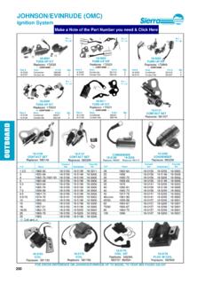
Transcription of ELECTRICAL SYSTEMS - boatfix.com
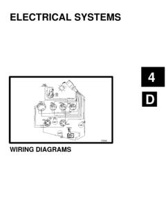
1 B471855 ELECTRICAL SYSTEMSIGNITION SYSTEM4B-0 - IGNITION system 90-823226--1 996 Table of ContentsPageThunderbolt IV (HEI) Ignition System4B-1.. Special Tools4B-1.. Torque Specifications4B-1.. Lubricants, Sealers and Adhesives4B-1.. Coil Specifications4B-1.. Exploded View for Thunderbolt IV Distributor For V-6 Engines4B-2.. MCM V-6 262 CID ( ) with Thunderbolt IV4B-3.. Replacement Parts Warning4B-4.. Spark Plugs4B-4.. Firing Order4B-4.. Distributor Advance Curves4B-4.. Repair4B-4.. Precautions4B-4.. Distributor Cap4B-5.. Rotor/Sensor Wheel4B-5.. Sensor4B-6.. Spark Plugs4B-7.. Ignition Module4B-8.. Spark Plug Wires4B-8.. Distributor Repair4B-8.. Removal4B-8.. Disassembly4B-8.. Reassembly4B-9.. Distributor Installation4B-9.
2 Engine Not Disturbed4B-9.. Engine Disturbed4B-10.. Ignition Timing4B-10.. Thunderbolt V Ignition System4B-11.. Identification4B-11.. General Description4B-12.. Idle Speed Spark Control4B-12.. Acceleration Spark Advance4B-12.. Mean-Best-Timing (MBT)Spark Advance4B-12.. Over-Speed Control4B-12.. Knock Retard Spark Control4B-12.. Thunderbolt V Spark Control Graph4B-13.. Circuit Description4B-14.. Ignition Control Module4B-14.. Knock Control Module4B-14.. Ignition Control system Timing Lead4B-14.. Ignition system Wiring Diagram4B-15.. Timing and Idle Adjustment Procedures ForThunderbolt V Ignition4B-16.. Setting Base Ignition Timing4B-16.. Adjusting Idle Mixture4B-16.. Adjusting Engine Idle Speed4B-16.. Troubleshooting Thunderbolt V Ignition4B-17.
3 Ignition Control Module /Coil /Distributor4B-17.. Knock Control Module4B-18.. Spark Plugs4B-19.. Spark Plug Wires4B-20.. IGNITION system - 4B-190-823226--1 996 Thunderbolt IV (HEI) Ignition System72722a - Ignition ModuleaSpecial ToolsMERCURY MARINE SPECIAL TOOLSDESCRIPTIONPART NUMBERT iming Light91-99379 Multi Meter/DVA91-99750 Torch Lamp91-63209 Insulating Compound92-41669 Quicksilver Liquid Neoprene92-25711-2 Torque SpecificationsDESCRIPTIONLb. mDistributor Clamp 3/8-162027 Spark Plugs (14mm)1520 Ignition Module Retaining Screws (Stainless Steel) , Sealers and AdhesivesDESCRIPTIONPART NUMBERL octite 271 Obtain LocallyThermalconductive GreaseObtain LocallyCoil SpecificationsCoil Part Number392-7803A4 Primary OhmsSecondary Ohms4B-2 - IGNITION system 90-823226--1 996 Exploded View for Thunderbolt IV Distributor For V-6 Engines720581152345768910111213141617181 9201 - Distributor Cap2 - Vent3 - Gasket4 - Rotor5 - Sensor Wheel6 - Screw (3)7 - E-Clip8 - Shaft9 - Screw (2)10- Lockwasher (2)11- Sensor12- Ignition Amplifier13- Screw (2)
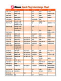
4 14- Distributor Housing15- Lockwasher16- Nut17- Gasket18- Washer19- Gear20- Roll PinIGNITION system - 4B-390-823226--1 996 MCM V-6 262 CID ( ) with Thunderbolt IVModule Part Number: 805361T-1 Identification Mark: V6-14 Module Advance: 14 Initial Timing: 8 BTDCT otal Advance: 22 5001000150020002500300035004000450050005 10 15 20 25 30 35 ENGINE SPARK ADVANCEMINUS INITIAL - IGNITION system 90-823226--1 996 Replacement Parts Warning!WARNINGE lectrical, ignition and fuel system componentson your MerCruiser are designed and manufac-tured to comply with Coast Guard Rules andRegulations to minimize risks of fire and of replacement ELECTRICAL , ignition or fuelsystem components, which do not comply withthese rules and regulations, could result in a fireor explosion hazard and should be / / +Spark In.
5 ( mm).045 In.( mm)Spark PlugTypeAC-MR43 TNGK-BR6 FSChampionRV8 CAC-MR43 LTSNGK-BPR6 EFSC hampionRS12 YCFiring Order72976 Firing Order 1-6-5-4-3-2 Distributor Advance Curves1. Distributor advance curve charts do not includethe initial engine timing. Basic initial timing mustbe added to chart for total advance The spark advance is controlled by the !WARNINGWhen performing the following procedure, besure to observe the following: Be sure that engine compartment is wellventilated and that no gasoline vapors arepresent, to avoid the possibility of fire. Be sure to keep hands, feet and clothingclear of moving parts. Do not touch or disconnect any ignitionsystem parts while engine is running. Do not reverse battery cable is negative ( ) ground.
6 Do not disconnect battery cables while en-gine is system - 4B-590-823226--1 996 Distributor Cap3. Loosen four distributor cap retaining Remove distributor Clean cap with warm soap and water and blow offwith compressed Check cap contact for excessive burning or cor-rosion. Check center contact for Check cap for cracks or carbon tracks using mag-neto Check condition of distributor cap gasket. Re-place gasket if damaged or If high tension leads are removed from cap referto Spark Plug Wires in this section and the fol-lowing illustrations for - Alignment Notch72978aa - VentRotor/Sensor Wheel1. Remove distributor rotor/sensor wheel assemblyfrom distributor shaft. Rotor and sensor wheelare secured to the shaft with Loctite.
7 Use two flatblade screwdrivers. The screwdrivers are posi-tioned opposite each other with the blade tips onthe underside of the rotor and sensor wheel as-sembly. Make sure blade tips are toward distribu-tor shaft until they come in contact with shaft. Adownward push on both screwdriver handles atthe same time will pry off rotor/sensor wheel as-sembly. The use of torch lamp will also aid in theremoval of the rotor/sensor wheel assembly.!WARNINGWear protective gloves when handling heated ro-tor/sensor wheel assembly to avoid With the rotor/sensor wheel assembly removed,inspect the locating key inside the The locating key will appear as a clean edged, 1/8in. (3 mm) wide, sloped ramp at the bottom of - Locating Keyb - Screws (Hex Head)c - Sensor Wheeld - Locating Pin4B-6 - IGNITION system 90-823226--1 9964.
8 If there is any doubt if sensor wheel is locatedproperly, lay sensor wheel on top of the figureabove with sensor fingers facing up (toward you).Line up three screw holes and locating pin holeon sensor wheel with the figure. If wheel is in-dexed properly all the fingers on wheel will line upwith those in the If there are pieces of material shaved off the keyor if it appears to have been damaged by beingforced down while misaligned with slot in distribu-tor shaft, the rotor must be Check rotor for burned or corroded center Check rotor for cracks and carbon tracks usingmagneto analyzer and instructions supplied If rotor is damaged, replace rotor by removingthree hex bolts and separating sensor wheel fromrotor.
9 Reinstall sensor wheel to new rotor makingsure locating pin on rotor is installed in locatinghole in sensor wheel. Tighten three hex bolts Bend carbon brush tang upward slightly until adistance of 1/4 in. ( mm) is obtained betweenrotor and - 1/4 in. ( mm)10. Put 2 drops of Loctite 271 or Quicksilver LoctiteType A into the rotor so it lands on the Put 2 drops of Loctite 271 in keyway on upperportion of distributor Immediately install rotor assembly onto distribu-tor shaft. Make sure rotor locating key is alignedwith keyway in distributor shaft before pressingrotor all the way down on the shaft, until it stops,with the palm of your hand. Let Loctite cure over-night with distributor in inverted The rotor should fit very tight.
10 It may be necessaryto heat rotor with torch lamp to properly install. Itis important not to let any Loctite run down distrib-utor shaft. Loctite could get into top distributorhousing Reinstall distributor cap on Install spark plug wires (if removed). Refer to Spark Plug Wires in this Remove rotor and sensor Remove two screws that hold sensor into distrib-utor Remove sensor from - Mounting Screwsb - Sensor AssemblyIGNITION system - 4B-790-823226--1 9964. Use a magnifying glass and light to inspect thetwo metal jumper leads for cracks. If a crack isfound in either metal jumper lead, install a - Jumper Leads!CAUTIONDo not use any type of silicone sealer on the in-side of the distributor.