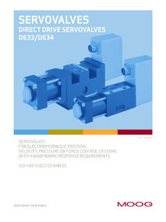
Transcription of Electrohydraulic Valves A Technical Look
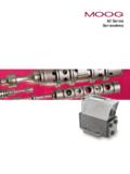
1 Electrohydraulic A Technical Look Electrohydraulic VALVE APPLICATIONS. Moog Inc. was the founded in 1951 by William C. Moog, inventor of the Electrohydraulic Servovalve. APPLICATIONS. His creation heralded a new era in precision control. It also spurred the growth of Moog to become the world leader Industrial Mobile/Marine in design and manufacture of Electrohydraulic control products Basic Metal Processing Active Suspension and systems. During the past decade the company has extended blow /Injection molding Forestry Machines its control expertise into Servo-Proportional Valves , Servo Earthquake Simulation Mining Machinery Electronics and Direct Drive Valves . Entertainment Equipment Railroads Moog products provide precise control of position, velocity Fatigue Testing Remote Control and force so important to the proper operation of a wide Flight Simulation Seismic Exploration variety of industrial machinery.
2 Gas, Steam & Hydro Turbines Ships Machine Tools Submersibles For example: Manufacturing Systems Vibration Reduction Moog Inc. Servoactuators accurately control the thickness Material Testing of steel slabs in continuous casting operations. Paper Machines Moog Inc. ServoJet Servo-Proportional Valves control both Robotics velocity and pressure in plastic injection molding machines Rubber Processing and wall thickness in plastic blow molding machines. Saw & Veneer Mill Machines Moog Inc. Direct Drive Valves control the thickness of paper Steel & Aluminum Mill Equipment on new state of the art paper machines. ENGINEERING ASSISTANCE. The information contained in this catalog presents typical products offered by Moog; our true expertise is helping you solve your motion control problems.
3 Our engineering staff is available to assist you in your efforts to accurately and precisely control position, velocity or force in your specific application. Often times this results in designing a customized design and product, specifi- cally suited to your need. Moog's capabilities in this respect are unmatched in industry. So call us and let us know how we can help you will be glad you did. Due to our policy of continual research and improvement, we reserve the right to change specifications in this catalog without notice. Applications Applications Each of these applications involves precise control of a com- plex structure, which in most cases is subject to varying loads that can adversely affect performance.
4 Moog products overcome the structural and load variation effects through the principles of feedback. Moog transducers measure the output, which could be position, velocity, pressure or acceleration and send signals to the machine signals are compared with the desired sensing and correcting on a continuous basis results in optimum system performance. 2. Electrohydraulic VALVE SELECTION GUIDE. Moog offers the broadest line of Electrohydraulic Valves on the market today. Our product line consists of Servovalves (Mechanical and Electric Feedback versions) and Servo- Proportional Valves (Direct Drive and Two Stage ServoJet . versions). Servovalves typically utilize a ISO10372 mounting pattern and are nearly always zero lapped or axis cut (no mechanical deadband).
5 Servo-Proportional Valves utilize an ISO4401 mounting pattern and may have a mechanical deadband. Selection of the proper valve involves understanding the performance requirements of your chart below attempts to categorize the more popular Moog valve series by two very important selection criteria flow and dynamic response. Selection Selection 1000. D665. 500. 400 D68X. D664. 300. D663. 79-200. 200 79-200 HR. D662. 100. 70 72. FLOW WITH 1000 psi SERVOVALVE DROP - gpm 50. DDV VALVE. D661 79-100. 40. 30. D634. 20. G761/D765 STD. D765 HR. 10. 7. D765 SHR. 5. 4. 3. SERVOVALVE. 2. 1 G631. D633. 5 7 10 20 30 40 50 70 100 200 300 400 500 700 1000. FREQUENCY OF SERVOVALVE 90 PHASE LAG Hz SERVOJET.
6 (SMALL TO MEDIUM SIGNAL RESPONSE). 3. HOW TO SELECT A SERVO OR PROPORTIONAL VALVE. DETERMINE THE REQUIRED VALVE FLOW RATE AND KEY PARAMETERS FOR SERVO OR PROPORTIONAL. FREQUENCY RESPONSE VALVE SELECTION. a) In order to compensate for unknown forces, size the actuator Supply Pressure area to produce a stall force 30% greater than the desired force Servovalve and ServoJet Valves are intended to operate with to the supply pressure available. constant supply pressure and require continuous pilot flow to maintain the hydraulic bridge supply pressure should where: A = actuator area (in2) be set so that the pressure drop across the valve is equal to one- third of the supply flow capacity should include the FR = force required to move continuous pilot flow to maintain the hydraulic bridge balance.
7 FR the load (lb) at maximum A= Direct Drive Valve performance is constant no matter what the PS velocity, ref. key parameters supply , they are good in systems with fluctuating PS = supply pressure (psi) supply pressures. Standard Moog Inc. Valves will operate at supply pressures Refer to the NFPA standard cylinder bore and rod sizes and from 200 to 3,000 psi. Optional Valves for 50 to 5,000 psi select the area closest to the result of the above calculations. operation are available. Refer to individual valve specifications. b)From the maximum required loaded velocity and the actuator area from the above calculation, determine the valve loaded Type of Fluid flow and the load pressure drop.
8 Moog Inc. Valves operate most effectively with fluids that exhibit a viscosity of 60 to 450 SUS at 100 F. Due to the Servovalve oper- where: ating range of -40 F to 275 F, care should be taken to assure fluid QL = loaded flow (in3/sec). QL = AXL viscosity does not exceed 6,000 SUS. In addition, fluid cleanliness is XL = maximum required of prime importance and should be maintained at ISO DIS 4406. loaded velocity (in/sec) Code 16/13 max, 14/11 recommended. Consult the Moog Inc. where: Filtration and Valve Series catalogs for recommendations. FR PL = load pressure drop (psi) Fluid compatibility with material used in the construction PL = of Valves must be considered. Contact the factory for specific A.
9 Information. c) Compute the no-load flow. Force Requirements In most applications, a portion of the available supply pressure PS where: must be used to overcome some force. Since valve flow ratings are QNL = QL QNL= no-load flow (in2/sec). PS - PL given as a function of pressure drop across the valve, total force requirements must be known in order to determine what portion d)Determine the valve rated flow at 1,000 psi valve drop for of the supply pressure is available to be dropped across the valve. Servovalves and 150 psi valve drop for Proportional Valves . Total force is the summation of all individual forces that occur due Increase by 10% for margin. to the static or dynamic configuration of the system.
10 10% pad where: FR = FL + FA + FE + FS where: QNL QR = Servovalve rated flow FR = total required force (lb). QR = ( ) (gpm) at 1,000 psi drop FL = force due to load (lb). or Proportional Valve rated flow at 150 psi drop FA = force due to acceleration (lb). in3/sec to gpm conversion FE = force due to external disturbance (lb). e) For open-loop control, a valve having a 90 phase lag at 3 Hz FS = force due to seal friction (lb). or higher, should be adequate. f) For closed loop control of systems utilizing electrical feedback, Force Due to a Load calculate the load natural frequency using the equations in this Force due to a load FL can be an aiding or resistive component, brochure under Load Resonant Frequency.