Transcription of ELECTRONIC LOCK INSTRUCTIONS (F INSTALLATION GUIDE
1 ELECTRONIC LOCK INSTRUCTIONS (FIELD INSTALLATION GUIDE )TDN 07103-00180 Feb 27 2009 COPYRIGHT NOTICE 2008 Delaware Capital Formation, Inc. All Rights Reserved. Triton Systems of Delaware, an operating company of Dover Electronics, Inc., a subsidiary of Dover Corporation (NYSE-DOV). DOVER, the DOVER logo and the Dover family of marks and TRITON, the TRITON logo and the Triton family of marks are registered trademarks of Delaware Capital Formation,Inc., a wholly owned subsidiary of Dover HEADQUARTERS522 E. Railroad Beach, MS 39560 Phone: (228) 868-1317 Fax: (228) 868-0437 ELECTRONIC LOCK INSTRUCTIONS2 PURPOSEThis GUIDE covers the steps for installing an ELECTRONIC lock assembly on all Business Hours andLevel 1 (Vault) ATMs (excluding Model 8100). This procedure includes a list of all tools andhardware necessary for the INSTALLATION as well as the steps procedure applies to all service personnel involved in the process of maintaining or convertingTriton #dna1#hcnerwelbatsujdAsreilpesoneldeeNhc nerwxob/tekcos)mm41("61/9dna)mm11("61/7 ELECTRONICLOCKKITN/P()06060-00160 DEILPPUSSTRAPSREBMUNTRAPNOITPIRCSEDYTITN AUQ71000-42630xoByrettaB/wdraGbmoC,kcoL1 30000-00310V9,yrettaB100000-00620steniba cHB-)mm62(" ,ssarB,eldnipS110000-00620mm45("8/1-2,ss arB,eldnipS)csiM-120000-00620lvL-)mm34(" ,ssarB,eldnipS1stenibac168100-45020daeh- talfspillihP)mm61("8/5,23-8#,wercS249410 -11030xoByrettaB,etalPtnuoM181300-45020h ctapnolyn/wdaeh-talF,)mm9("8/3,23-8,werc S120200-45020hctap/wdaeh-talF,)mm6("4/1x ,23-6#,wercS196100-45020rehsawtxe/wdaeh- spillihpnaP,)
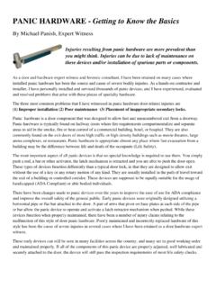
2 Mm9("8/3,23-8#,wercS481410-11030,msinahc eMkcoL,ytiruceS,etalPtlobdaeD151000-2703 0"6,parWyT380000-27030kcaBevisehdA,tsoPp arWyT308100-30170snoitcurtsnIkcoLcinortc elE13 ELECTRONIC LOCK INSTRUCTIONSINSTALLATION OF THE ELECTRONIC LOCK ASSEMBLY[ BUSINESS HOURS (BH) AND LEVEL 1 (VAULT) CABINET ATMS]REMOVAL OF MECHANICAL COMBINATION power to the unit and open the security container (For cabinets with T-Handles) Remove the door panel from the rear of the door by firstremoving the two large Phillips screws (or 9/16" bolts) located in the center of the door panel andthe six #8 Phillips screws located at the top and bottom of the door the two (2) screws which attach the deadbolt cover to the deadbolt and remove the brass shaft key located in the center of the spindle by pulling directly out on itwith a pair of pliers (see Figure 1). Unscrew the outer combination dial from the black spindlewheel and remove both the dial and the wheel from the lock remove the lock on a Level 1 (Vault) cabinet, open the safe and remove the latchwork cover ifnecessary.)
3 Remove the relocker bracket. Move the bolt works to the closed(Locked) position allowing thespring loaded pin to fire. This will ensure the door cannot be accidentally closed and the four (4) mounting screws which attach the deadbolt assembly to the inside ofthe door and remove the deadbolt the two screws which attach the dial plate to the front door and remove the screwsMounting screwsFigure 1. Mechanical lock with cover LOCK INSTRUCTIONS4 INSTALLATION OF THE ELECTRONIC all units, attach the face mounting plate to the outside of the door using the two shoul-der screws (or screws with brass sleeves) supplied. Make sure the word UP stamped on the front ofthe face plate is facing up when the mounting holes are positioned vertically (see Figure 2).Figure 2. Vertically mounted ELECTRONIC (3) brass lock spindles are supplied with the INSTALLATION kit. Only one of the brassspindles will be used for the particular cabinet (BH or Lvl 1) which the lock will be installed.
4 Todetermine which spindle to use, look at the spindle sizes below. The shortest spindle is used onBusiness Hours cabinets while the middle size is used on Level 1 (Vault) cabinets. Find thematching spindle in the kit and discard the : The longest spindle may be used/modified for cabinet configurations where the other 2spindles are not 02600-00000P/N 02600-00002P/N 02600-000015 ELECTRONIC LOCK the end of the combination panel lead through the center of the second plastic bush-ing. Make sure the flat side of the bushing is facing the door. Slide the bushing down the spindle so thatthe channel in the spindle is aligned with the slot in the the deadbolt assembly onto the spindle and attach to the back of the door using the mount-ing screws supplied. Make sure the combination panel lead exits from the bottom of the the combination panel lead into the top receptacle on the deadbolt connector. Make surethe connection is secure by gently pulling on the wire to make sure it does not disconnect from the battery box and install the 9 volt battery.
5 Connect the plug on the end of the batterybox lead into the lower receptacle on the deadbolt connector. Again, check to make sure the connectionis secure. Recommend clean the back of the door at the area where the battery box will be installed withan alcohol pad, if available. Remove the backing from the tape on the back of the battery box and pressthe box firmly onto the door. Make sure there is some slack in the battery Level 1 (Vault) cabinets, a notch is cut in the latchwork cover to allow the battery box to beplaced outside the latchwork. Make sure when putting the latchwork cover back onto the unit, that thewire passes through this the tie wrap posts to the back of the door along the length of the battery cable and tiewrap both the battery cable and the combination panel cable to the tie wrap posts. Some unitsalready have tie wrap posts welded to the inside of the door to tie wrap the cables to. Make surethe cables do not interfere with the latchwork.
6 Enter the default combination 1-2-3-4-5-6 andturn the combination dial clockwise to open the lock and then lift/turn the handle. Make surethe lock operates properly before shutting the safe door !!! the latchwork cover back onto the door. Make sure to install the relocker mecha-nism back onto the lock on Level 1 cabinet units before installing the the brass spindle into the rear of the combination face plate making sure that thechannel in the spindle is aligned with the wire exiting the back of the the plastic panel bushing down over the panel connector on the end of the panel wire anddown over the spindle. Make sure that the two alignment holes on the bushing mate with the posts on therear of the combination panel, and the flat side of the bushing is facing the the panel lead through the front of the security container door and then insert the combina-tion panel onto the shoulder screws (or screws with brass sleeves) which attach the combination mount-ing plate to the front of the door.
7 Turn the combination dial clockwise until the dial stops, then turn thedial counterclockwise until the numbers are aligned either vertically or horizontally (depending on themodel of the cabinet). Refer to Figure 2 for assembly of the LOCK INSTRUCTIONS6 OPERATING THE ELECTRONIC LOCK (LAGARD)The ELECTRONIC lock combination consists of six digits. Upon arrival, the combination of the lock should already bepreset to THE the preset combination and check for proper operation. After each keypress, the lock will beep. After the finaldigit has been entered, the lock will beep twice, and the open period will a valid combination has been entered, the operator will have approximately 4 seconds to open the open the lock, turn the dial the lock is opened, the cabinet door may be FEATUREThe lock includes a Wrong Try Penalty lockout feature that prevents entry from unauthorized personnel. Thisfeature performs as follows: Entry of four (4) consecutive invalid combinations starts a 5-minute delay flashes red at ten (10) second intervals.
8 At the end of the delay period, two (2) more consecutive invalid combinations will restart an additional THE COMBINATIONTo change the combination of the lock, simply follow these six (6) zeros 0 . the current combination (initially set at 1-2-3-4-5-6). the new six (6) digit combination a mistake is made, wait thirty (30) seconds and repeat the first 3 lock combination several times before closing the door. The combination is now Code Entry - Double signal after valid six (6) digit code is Code Entry - Triple signal and old code is still valid.