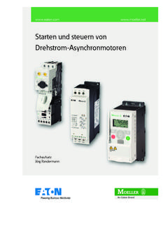
Transcription of Electronic motor starters and drives - Eaton Electrical
1 Eaton Wiring Manual 06/112-1222 Electronic motor starters and drives PageDrives engineering basic information 2-2 Soft starter basic information 2-9 Connection example DS7 2-26DM4 connection example 2-44 Frequency inverter basic information 2-66 Connection example for M-Max 2-85 Rapid Link System 2-98 Eaton Wiring Manual 06/112-2 Electronic motor starters and drives222 drives engineering basic information drives egineering selection criteriaEach drive task requires a drive motor . The speed, torque and controllability of each motor must fulfill the requirements of the task. As a general rule, the application determines the drive motor most frequently used worldwide in industrial plants and large buildings is the three-phase asynchronous motor . Its robust and simple construction as well as its high degrees of protection and standard types are the main features of this inexpensive electric asynchronous motorMotor starting variants Direct-on-line start In the simplest case the motor is connected directly with a contactor.
2 The combination of motor protection and cable protection (fuse) is called a motor starter (MSC = motor starter Combination).By applying the full mains voltage to the motor windings, DOL starting may produce large starting currents which may result in troublesome voltage changes. Direct-on-line starting three-phase motors must not cause interference voltage changes in the public utility grid. This requirement is generally fulfilled if the apparent power of a three-phase asynchronous motor does not exceed kVA or its startup current does not exceed 60 A. With a mains voltage of 400 V and 8 times the starting current, this corresponds to a rated motor current of around A and thus a motor rating of 4 kW. The motor rating denotes the mechanical output of the motor at the shaft. Star-delta starter This is the most popular and commonly used starting method for motor ratings > 4 kW (400 V).
3 Electronic motor starter (EMS) and soft starter These enable the soft and low-noise starting of the motor . This eliminates interference producing current peaks and jerks during switching. The startup and deceleration phase of the motor can also be time-controlled depending on the load. Frequency inverter This enables time-controlled motor starting, motor braking and operation with infinitely variable motor speeds. Depending on the application, different types of frequency inverters are used: with the voltage/frequency control (U/f) or vector control for frequency-controlled motor operation, with vector control or servo control for high speed accuracy and additional torque circuit diagrams page 2-3 Electronic motor starters and drivesDrives engineering basic informationEaton Wiring Manual 06/112-3222B1: Speed measuring (pulse generator)F1: Fuse protection(short- circuit and cable protection)F2: motor protection (protection from thermal overload, overload relay)M1: Three-phase asynchronous motorQ1: Switching(contactor, motor contactor)Q2: Soft starter , Electronic motorstarter T1.
4 Frequency inverterMotor connectionWhen connecting a three-phase motor to the mains supply, the data on the rating plate of the motor must correspond to the mains voltage and standard connection is implemented via six screw terminals in the terminal box of the motor and with two types of circuit , the star connection and the delta connection, depending on the mains voltage. M F13 / N / PE / AC 50/60 HzQ1F2M13~MB1T1Q23~M 3~M 3~ U1V1W1W2U2V2 Electronic motor starters and drivesDrives engineering basic informationEaton Wiring Manual 06/112-4222 The rotation direction of a motor is always determined by directly looking at the drive shaft of the motor (from the drive end). On motors with two shaft ends, the driving end is denoted with D (= drive ), the non-driving end with N (= No drive ).
5 Regardless of the circuit type and the type of three-phase asynchronous motor , the connections must be labeled, so that their alphabetical sequence ( U1, V1, W1) corresponds with the order of the mains voltage sequence (L1, L2, L3) and causes the motor to rotate clockwise. On the three-phase asynchronous motor , three windings are arranged offset from each other by 120 /p (p = number of pole pairs). When a three-phase AC voltage with a 120 phase sequence is applied, this produces a rotation field in the effect of inductance causes the rotation field and torque to be formed in the rotor winding. The speed of the motor thus depends on the number of pole pairs and the frequency of the supply voltage. The rotation direction can be reversed by swapping over two of the supply on the rating plateThe Electrical and mechanical rating data of the motor must be stated on its rating plate (IEC 34-1, VDE 0530).
6 The data on the rating plate describes the stationary operation of the motor in the area of its operating point (MN, at 400 V and 50 Hz). The operating data is unstable in the motor start following examples show the rating plates for two motors with a motor shaft output of 4 kW and the respective connection circuits on a three-phase AC network with 400 V and 50 0L1L2L3360 L1120 120 120 180 270 Clockwise (FWD)Anticlockwise operation (REV)FWD = forward run (clockwise rotationfield)REV = reverse run (anticlockwise rotation field active)L1L2L3U1V2W3L1L2L3U1V2W3 Electronic motor starters and drivesDrives engineering basic informationEaton Wiring Manual 06/112-5222 Star circuitDelta circuit , , With the specified 230/400 V voltage, this motor must be connected to the three-phase supply (ULN = 400 V) in a star configuration.
7 With the specified 400/690 V voltage, this motor must be connected to the three-phase supply (ULN = 400 V) in a delta configuration. The voltage of each motor winding is designed for 230 V. The windings must therefore be connected in sequence to the phase voltage (400 V). Each motor winding is designed here for the maximum phase voltage of 400 V and can be connected directly. The three winding phases (W2-U2-V2) are configured in the terminal box to the so-called star point. The voltage of the individual phases to the star point is 230 V (= UW). The three winding phases (U1 W2, V1 U2, W1 V2) are combined in the terminal box and connected directly to the individual min-1230 / 400 / A50 HzIP 54 Iso. KI KWS1cos / 1410 min-1400 / 690 / A50 HzIP 54 Iso.
8 KI KWS1cos / L1L3L2V1V2U1W1W2U2 ULNILNL1L3L2U1W1V1V2W2U2 ULNILNULN3UW =ILNIW=ULNUW=ILN3IW =U1V1W1W2U2V2U1V1W1W2U2V2 Electronic motor starters and drivesDrives engineering basic informationEaton Wiring Manual 06/112-6222 Startup characteristicsThe following figure shows the characteristic startup curves of a three-phase asynchronous : Starting currentIN: Rated operational current at theoperating pointMA: Starting torqueMB: Accelerating torque (MM > ML)MK: Breakdown torqueML: Load torqueMM: motor torqueMN: Rated load torque, (stable operatingpoint, intersection point of the three-phase speed torque characteristicwith the load characteristic)MS: Pull-up torquen: Speed (actual value)nN: Rated speed at the operating pointnS: Synchronous speed (nS - nN = slip speed s)Synchronous speed:Slip speed in %:Three-phase asynchronous motor speed:fFrequency of voltage in Hz (= s-1)n Speed in of pole pairss: Slip speed in power:P1: Electrical power in WU:Rated operating voltage in VI:Rated operational current in Acos : Power factorMotor output (power equation): P2: Mechanical shaft output power in kWMN: Rated torque in Nmn: Speed in.
9 Comparison of startup variantsThe features of the startup variants to described on page 2-2 are shown on the following pages 2-6 and graphs show the typical , I0nsfp---=snsn ns--------------100 % =nfp---1s =P1UI 3 cos =P2 MNn 9550-----------------= P2P1-----= Electronic motor starters and drivesDrives engineering basic informationEaton Wiring Manual 06/112-7222 Direct motor start Voltage curve Mains load highCurrent curve Relative startup current4 to 8 x Ie (depending on motor )Torque behaviour Relative startup torque to 3 x MN (depending on the motor ) Features: Strong acceleration with large starting current High mechanical load Scope of application: drives on powerful supply networks that allow high starting currents (torques)Star-delta starter Voltage curve Medium mains loadCurrent curve Relative starting to 3 x Ie (~ compared to DOL start)Torque behaviour Relative starting torque to 1 x MN (~ compared to DOL start) Features: Startup with reduced current and torque Current, torque peak on switching Application range.
10 drives that are only subject to loads after the startup100 %tU246I / 1 MLM/MN100 %58 %tU 246I / 123M/ 1 Electronic motor starters and drivesDrives engineering basic informationEaton Wiring Manual 06/112-8222 Soft starters Voltage curve Low to medium mains loadCurrent curve Relative starting current 2 to 6 x Ie (reduced by voltage control)Torque behaviour Relative starting torque to 1 x MN (M ~ U2, quadratically adjustable by voltage control) Features: adjustable starting characteristics controlled deceleration possible Application rangeDrives with starting behavior adjusted to working inverter Voltage curve Low mains loadCurrent curve Relative starting current 1 to 2 x Ie (adjustable)Torque behaviour Relative starting torque ~ to 2 x MN (M ~ U/f, adjustable torque) Features: high torque at low current adjustable starting characteristics Application range.