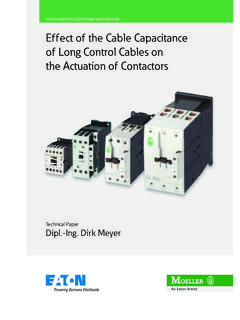
Transcription of Standards, formulae, tables - Eaton
1 Eaton Wiring Manual 06/1110-11010 standards , formulae , tables PageMarking of electrical equipment 10-2 Protective measures 10-4 Overcurrent protection of cables and conductors 10-12 Electrical equipment of machines 10-21 Measures for risk reduction 10-27 Protection types for electrical equipment 10-29 Utilization categories for switching elements 10-34 Utilization categories for contactors and motor starters 10-36 Utilization categories for switch-disconnectors 10-40 Rated motor currents
2 10-43 Conductors 10-46 formulae 10-54 International Unit System 10-58 Eaton Wiring Manual 06/1110-2 standards , formulae , tables1010 Marking of electrical equipment Marking to DIN EN 81346-2 (IEC 81346-2) Eaton uses the above the method of marking up to now, the function of the electrical equipment in the respective circuit primarly determines the cose letter. This means that there is some freedom in the selection of the code of a resistor Normal current limiter: R Heater resistor: E Measurement resistor: BIn addition to that, Eaton specific decisions have been made with regard to the interpretation of the standard that sometimes deviate from the standard.
3 The marking of connection terminals are not readable from the right. A second code letter for the marking of the use of the equipment is not given, : timing relay K1T becomes K1. Circuit-breakers with the main function of protection are still marked with are numbered from 1 to 10 from the top left. Contactors are newly marked with Q and numbered from 11 to nn. : K91M becomes Q21. Contactor relays remain K and are numbered from 1 to n. The marking appears in a suitable position as close as possible to the circuit symbol. The marking forms the link between the equipment in the installation and the various circuit documents (wiring diagrams, parts lists, circuit diagrams, instructions). For simpler maintenance, the complete marking or part of it, can be affixed on or near to the equipment with a comparison of the Eaton used code letters old new table , page 10-3 standards , formulae , tablesMarking of electrical equipmentEaton Wiring Manual 06/1110-31010 Code letter PurposeExamples for electrical equipmentA(several purposes) (without main purpose)BSignal generationPressure switches.
4 Limit switchesCStorageCapacitorsD(reserved for later)EEnergy supplyHeating resistor, lampsFProtectionBimetal releases, fusesGPower supplyGenerator, UPSH(reserved for later)I(must not be used)J(reserved for later)KPSignal processingContactor relay, timing relaysL(reserved for later)MDrive energyMotorN(reserved for later)O(must not be used)PInformation displaySignalling and measuring devicesQSwitching energy / signal flowSoft starter, contactor, motor starterREnergy flow limitationReactor coils, diodesSManual signal generationControl circuit devicesTEnergy conversionFrequency inverters, transformerUObject fixingVMaterial processingElectro filter WPower transmissionXObject connectionTerminal, plug connectorY, Z(reserved for later) Eaton Wiring Manual 06/1110-4 standards , formulae , tables1010 Protective measuresProtection against electrical shock to IEC 60364 -4-41/DIN VDE 0100-410 This is divided into basic protection (previously protection against direct contact), fault protection (previously protection against indirect contact) and protection against both direct and indirect contact.
5 Basic protectionThese are all the measures for the protection of personnel and working animals from dangers which may arise from contact with live parts of electrical equipment. Fault protectionThis is the protection of personnel and working animals from fault scenarios which may arise from accidental contact with components or extraneous conductive parts. Additional protectionIf basic or fault protection fails or there is a greater potential danger, residual current protective devices with I n 30 mA offer additional must be ensured by either a) the equipment itself or b) the use of protective measures when erecting the installation or c) a combination of a) and b).If basic, fault and additional protection is combined in a suitable manner the following protective measures result and are covered in section 410 of DIN VDE 0100: Automatic disconnection of the power supply (0100-411) Double or reinforced insulation (0100-412) Protective separation (0100-413) Safety extra low voltage SELV or PELV (0100-414)One of the key amendments to DIN VDE 0100-410 of June 2007 was the additional protection for final circuits for outdoor areas and sockets ( ).
6 This stipulates that an additional protection must be provided by means of residual current devices (RCDs) with I n 30 mA for sockets 20 A, as well as final current circuits for portable equipment 32 A used outdoors. The previous recommendation has therefore been changed to a mandatory requirement in order to increase , formulae , tablesProtective measuresEaton Wiring Manual 06/1110-51010 Protection against indirect contact by means of disconnection or indication The conditions for disconnection are determined by the type of system in use and the protective device to IEC 60364 -1/DIN VDE 0100-100 RBEarthing on the current sourceRAEarthing on chassis of electrical equipmentEarth continuity type systemsMeaning of designationTN systemT: Direct earthing of a pointN: Chassis (of electrical equipment) directly connected with the power supply system earthTT systemT: Direct earthing of a pointT: Direct electrical connection of chassis to earth, independent of any existing earthing of the power supply systemIT systemI.
7 All live parts isolated from earth or one point connected to earth via a high impedanceT: Direct electrical connection of chassis to earth, independent of any existing earthing of the power supply systemL2NL1L3 PERBL2NL1L3 RBRAL2L1L3 RAStandards, formulae , tablesProtective measuresEaton Wiring Manual 06/1110-61010 Protective devices and conditions for disconnection to IEC 60364 -4-41/DIN VDE 0100-410 Type of distribution systemTN systemProtection withCircuit principleCondition for disconnectionOvercurrent protective deviceTN-S systemseparated neutral and protective conductors throughout the systemZsxIa U0 withZs = Impedance of the fault circuitIa = Current, which causes switch off in ( ): 5 s sU0 = rated voltage against earthed conductorFuses,miniature circuit-breakers,circuit-breakersTN-C systemNeutral conductor and protection functions are combined throughout the system in a single PEN , formulae , tablesProtective measuresEaton Wiring Manual 06/1110-71010 Protective devices and conditions for disconnection to IEC 60364 -4-41/DIN VDE 0100-410 1) table , page 10-11 Type of distribution systemTN systemProtection withCircuit principleCondition for disconnectionOvercurrent protective deviceTN-C-S systemNeutral conductor and protective conductor functions are in a part of the system combined in a single PEN current protective device Zs x I n U0 withI n = Rated fault currentU0 = Maximum permissible touch voltage1).
8 ( 50 V AC, 120 V DC)L2L1L3 NPE(N)L2L1L3 NPE(N) standards , formulae , tablesProtective measuresEaton Wiring Manual 06/1110-81010 Protective devices and conditions for disconnection to IEC 60364 -4-41/DIN VDE 0100-410 1) table , page 10-11 Type of distribution systemTT systemProtection withCircuit principleConditions for indication/disconnectionResidual current device(General case)RA x I n UL withRA = Earthing resistance of conductive parts of the chassis (total)I n = Rated fault currentUL = Maximum permissible touch voltage1):( 50 V AC, 120 V DC)Overcurrent protective deviceFuses,miniature circuit-breakers,Circuit-breakers (special case)RA x Ia UL withIa = Current which causes automatic disconnection in 5 sL2 PEL1L3NL2L1L3 NPEPEFIFIFIL2 PEL1L3 NPEPES tandards, formulae , tablesProtective measuresEaton Wiring Manual 06/1110-91010 Protective devices and conditions for disconnection to IEC 60364 -4-41/DIN VDE 0100-410 1) table , page 10-11 Type of distribution systemTT systemProtection withCircuit principleConditions for indication/disconnectionOvercurrent protective device (always with additional insulation monitoring device, see below)RA x Id UL (1)ZS x Ia Uo(2)
9 RA = Earthing resistance of all conductive parts connected to an earthId = Fault current in the event of the first fault with a negligible impedance between a phase conductor and the protective conductor or element connected to itUL = Maximum permissible touch voltage1): 50 V AC, 120 V DCL2 PEL1L3 standards , formulae , tablesProtective measuresEaton Wiring Manual 06/1110-101010 Protective devices and conditions for disconnection to IEC 60364 -4-41/DIN VDE 0100-410 Type of distribution systemIT systemProtection withCircuit principleConditions for indication/disconnectionResidual current device (RCD) (always with additional insulation monitoring device, see below)RA x I n ULI n = Rated fault currentInsulation monitoring device (IMD) additional potential equalizationThe insulation monitoring device is used to display the insulation state of all live parts to earth.
10 An indication (visual/acoustic) is generated if the resistance goes below a specific value (R). The system is not disconnected but remains operational until a second earth fault occurs and the automatic disconnection takes < standards , formulae , tablesProtective measuresEaton Wiring Manual 06/1110-111010 The protective device must automatically disconnect the faulty part of the installation. At no part of the installation may there be a touch voltage or an effective duration greater than that specified in the table below. Maximum disconnection times (s) as a function of the rated voltage. Phase conductors to earth and the system in accordance with VDE is the rated operating voltage phase conductor to :A disconnection may be necessary for different reasons than the protection from electric permissible disconnection time [s]DDMax. permissible disconnection time [s]50 V < U0 120 (see note)(see note)120 V < U0 230 V < U0 400 > 400 Wiring Manual 06/1110-12 standards , formulae , tables1010 Overcurrent protection of cables and conductors Cables and conductors must be protected by means of overcurrent protective devices against excessive temperature rises, which may result both from operational overloading and from short-circuit.