Transcription of Energi Savr Node for 0–10 V with Softswitch SPEC (369241)
1 specification SUBMITTALPageJob Name:Job Number:Model Numbers: Energi Savr Node QSN0 10 V-/ Softswitch Fixture Controllers369241k 1 Savr Node for 0 10 V- Energi Savr Node with SoftswitchThe Energi Savr Node (ESN) family is a group of modular products for the control of lighting and other loads. This document describes the following products: ESN unit for 0 10 V- (models QSN-4T16-S and QSN-4T16-S-347 0 10 V- Control / Softswitch ) Softswitch ESN unit (models QSN-4S16-S and QSN-4S16-S-347 Softswitch )Features Default configuration requires no commissioning. Programming using integral interface on the ESN unit. Four occupancy sensor inputs for automated control of lights in 4 zones. Four daylight sensor inputs automatically adjust light levels based on the amount of natural light entering through the windows. Four IR receiver inputs for personal control.
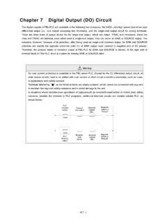
2 Four inputs for IEC PELV / NEC Class 2 dry contact switches. I ncludes QS control link for seamless integration of lights, control stations, and QS sensor modules. Softswitch technology yields 1,000,000 cycle relay lifetime. Contact Lutron for compatibility with Quantum ExampleQS linkControl Power120 277 V~Load Input Feeds (4) 120 277 V~; 347 V~30 10 V Channels (4)QSN-4T16-S and QSN-4T16-S-347 Emergency Contact Closure InputContact Closure InputSwitched Load Outputs (4) 16 A Softswitch 120 277 V~; 347 V~3 Wireless CommunicationWired Daylight Sensors (up to 4)2 Wired Daylight Sensors (up to 4)1,2 Wired Occupancy Sensors (up to 4)Wired Occupancy Sensors (up to 4)1 Wired Wallstation or IR receivers (up to 4)Wired Wallstation or IR Receivers (up to 4)1 IEC PELV / NECR Class 2 Dry Contact Switch (up to 4) (by others)IR TransmitterIR TransmitterOROROROR Notes: 1 Up to 4 wired sensors total (of any type).
3 2 The maximum number of daylight sensors (wired and wireless) that an ESN unit can support is four (1 per zone).3 For 347 V~ models QS WallstationESN Programming InterfaceRadio Powr Savr Occupancy Sensor (up to 10 per QSM)Radio Powr Savr Daylight Sensor (up to 10 per QSM)2 Pico Wireless Controller (up to 10 per QSM) specification SUBMITTALPageJob Name:Job Number:Model Numbers: Energi Savr Node QSN0 10 V-/ Softswitch Fixture Controllers369241k 2 Approvals UL Listed CSA NOM Lutron Quality Systems registered to ISO 9001:2015 Complies with requirements for use in other spaces used for environmental air (plenums) per NEC 2014 (C)(3) Meets the Canadian National Building Code plenum requirements for a concealed space used as a plenum within a floor or roof assembly For commercial use, Class A onlyPower Control Power: 120 V~; 220 240 V~; 277 V~ 50 / 60 Hz Lightning strike protection meets ANSI / IEEE standard Can withstand voltage surges of up to 6,000 V~ and current surges of up to 3,000 A Current draw: A max 10-year power failure memory: restores lighting to levels prior to power interruption Latching relays keep previously illuminated zones on when control power feed is lostEnvironment Ambient Temperature Operating Range: 32 F to 104 F (0 C to 40 C) Relative humidity: less than 90% non-condensing For indoor use only Thermal dissipation: 40 BTU/hrTerminal Wiring Control Power Wiring: 14 AWG to 12 AWG ( mm2 to mm2) Load Wiring: 14 AWG to 12 AWG ( mm2 to mm2) 0 10 V- Wiring: 20 AWG to 12 AWG ( mm2 to mm2) I nput Group Wiring: 20 AWG to 12 AWG ( mm2 to mm2) maximum wire run length to each input not to exceed 150 ft (46 m) QS Link Wiring.
4 22 AWG to 12 AWG ( mm2 to mm2) Contact Closure Wiring: 20 AWG to 12 AWG ( mm2 to mm2)Physical Design and Mounting NEMA Type 1, IP-20 protection Surface mountLoad Types (relay ratings) 16 A Tungsten, 120 to 277 V~ 16 A AC General Use, 120 to 277 V~ 16 A Electric Discharge Lamp (ballast), 120 to 277 V~, 347 V~ (347 V~ models only) 16 A Inductive, 120 to 277 V~ HP, 120 V~ HP, 220 to 277 V~ Works with all ballasts and drivers that provide a current source that is compliant to IEC 60629 Annex , and whose inrush current does not exceed NEMA410 standards for electronic ballast/driver Input Default AssociationsInputs/OutputsZone 1 Zone 2 Zone 3 Zone 4 Group 1 OccXPhotoXIRXS witchXGroup 2 OccXPhotoXIRXS witchXGroup 3 OccXPhotoXIRXS witchXGroup 4 OccXPhotoXIRXS witchXCCIXXXXE mergency CCIXXXX Softswitch : 120 V~ to 277 V~, 347 V~ (347 V~ models only) Softswitch relay is rated for 16 A continuous use per channel, which is the maximum continuous load for a 20 A Overcurrent Protection Device (Branch Breaker).
5 Patented Softswitch circuit eliminates arcing at mechanical contacts when loads are switched. Extends relay life to an average of 1,000,000 cycles (on / off) for resistive, capacitive, or inductive sources. Relay is mechanically held. specification SUBMITTALPageJob Name:Job Number:Model Numbers: Energi Savr Node QSN0 10 V-/ Softswitch Fixture Controllers369241k 3 Specifications (continued) 0 10 V- Product Ratings (QSN-4T16-S and QSN-4T16-S-347) Each output sinks up to 50 mA maximum. Each output sinks current only (load device must provide 10 V- supply). Provides an IEC PELV / NEC Class 2 isolated 0 10 V- output signal that conforms to IEC 60929. Occupancy Sensors Up to 16 occupancy sensors can be programmed to the ESN device. Manual Programming: up to 4 occupancy sensors wired directly to the ESN device, up to 4 occupancy sensors wired to a QS Sensor Module (QSM), and up to 10 wireless occupancy sensors through the same QSM; the total programmed to the ESN device cannot exceed 16.
6 HHD (iPod / iPhone) Programming: up to 16 occupancy sensors from any source (wired directly to the ESN device, wired to any other ESN device, or wired / wireless from any QSM on the QS link); the total programmed to the ESN device cannot exceed 16. Use Lutron occupancy sensors to control one or more zones. Use Lutron occupancy sensors in vacancy mode to automatically turn the lights off in an area after it becomes vacant. Each zone can be programmed to automatically turn the lights on when occupied and turn the lights off when vacant. Each wired occupancy input can power one Lutron occupancy sensor. Each occupied scene and unoccupied scene can be programmed independently. Lutron occupancy sensors can be programmed to automatically turn the lights on in area when it becomes occupied and turn the lights off in an area after it becomes vacant. Each of the four occupancy inputs can power one Lutron occupant sensor.
7 Each area s occupied scene and unoccupied scene can be programmed independently. Occupancy sensor must provide a dry contact closure or solid-state output. Additional occupancy sensors can be used with the ESN device. Refer to the Programming Options and Features table for system rules. seeTouch QS Controls seeTouch QS wallstations can be configured to control ESN unit scenes or zones. I n zone toggle mode, zone buttons can be assigned to one or more zones on any ESN unit connected to the QS Link. I n scene mode, wallstations can be assigned to one or more ESN units connected to the QS Link. LED indicator displays zone or scene 1: seeTouch QS Wallstation Configurations# ButtonsWallstation Function12357 Zone Toggle Scene1, Off (toggle)1, Off1, 2 Off1-4, OffN/A I R Wallstation or Receiver Input Four inputs for IR receivers or wallstations for control of lighting zones can be connected directly to the ESN unit.
8 Use Lutron CC-1 BRL-WH or CC-4 BRL-WH wallstations to control one or more zones. Use Lutron EC-DIR-WH or EC-IR-WH ceiling mount sensors to control one or more zones. Up to four additional wired wallstations or IR receivers can be assigned when associated with a QSM. Associate additional QSMs and sensors/controls with ESN unit when programming with an Apple iPod touch or iPhone. Refer to "Programming Options" section for details. Apple, iPhone and iPod touch are trademarks of Apple Inc., registered in the and other countries. specification SUBMITTALPageJob Name:Job Number:Model Numbers: Energi Savr Node QSN0 10 V-/ Softswitch Fixture Controllers369241k 4 (continued) Daylight Sensors Lutron daylight sensors allow daylight harvesting with programmable effect on light output. Four daylight sensors can be connected directly to the ESN unit. Use Lutron EC-DIR-WH sensors to control one or more zones.
9 Alternatively, up to four sensors (Lutron Wired Daylight Sensors or Radio Powr Savr Daylight Sensors) can be assigned when associated with a QSM. The maximum number of Lutron daylight sensors (wired or wireless), either wired directly to the unit or indirectly (associated with a QSM) cannot exceed four. Associate additional QSMs and sensors/controls with ESN unit when programming with an Apple iPod touch or iPhone. Refer to "Programming Options" section for details. Contact Closure Input (CCI) Default behavior: Activate scenes using momentary or maintained closures from an external device such as a timeclock. Start or stop Afterhours Mode using a maintained closure. The attached device must provide a dry contact closure or solid-state output. Configurable for Normally-Open (NO) or Normally-Closed (NC) operation. I nput is miswire-protected up to 36 Contact Closure Input By default, contact closure input from Lutron Emergency Lighting Interface (LUT-ELI-3PH), security, or fire alarm systems turns all zones on to full output when emergency state is detected.
10 Emergency contact closure input is normally closed (NC). The ESN unit is shipped with a jumper pre-installed. Response of each zone is configurable. Attached devices, by default, will go to maximum output and ignore control inputs. No operations will be allowed until emergency signal is cleared. The attached device must provide a dry contact closure or solid-state output. I nput is miswire-protected up to 36 V-. Emergency CCI cannot control other ESN with GRAFIK Eye QS ESN unit follows GRAFIK Eye QS scene activations when associated with the GRAFIK Eye QS. ESN unit responds to commands initiated by the GRAFIK Eye QS astronomic time clock when associated with the GRAFIK Eye QS. ESN unit operates in afterhours mode when associated with a GRAFIK Eye QS that is in afterhours with QSE-IO ESN unit responds to scene commands initiated by the QSE-IO, if the QSE-IO DIP switches have been set to either scene selection mode, zone toggle mode, partition mode, or occupancy sensor with QSE-CI-NWK-E I ntegrate ESN unit with touchscreens, PCs, A / V systems, or other digital systems and devices.