Transcription of Engineering Analysis with SolidWorks Simulation 2012
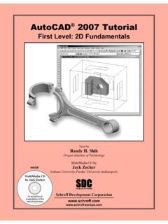
1 Engineering Analysis with SolidWorks Simulation 2012 Paul M. Kurowski SDCPUBLICATIONS Textbooks. Lower Development CorporationVisit the following websites to learn more about this book: Engineering Analysis with SolidWorks Simulation 2012 31 2: Static Analysis of a plate Topics covered Using the SolidWorks Simulation interface Linear static Analysis with solid elements Controlling discretization error with the convergence process Finding reaction forces Presenting FEA results in a desired format Project description A steel plate is supported and loaded, as shown in Figure 2-1. We assume that the support is rigid (this is also called built-in support, fixed support or fixed restraint) and that a 100000N tensile load is uniformly distributed along the end face, opposite to the supported face. Figure 2-1: SolidWorks model of a rectangular plate with a hole.
2 We will perform a displacement and stress Analysis using meshes with different element sizes. Notice that repetitive Analysis with different meshes does not represent standard practice in FEA. However, repetitive Analysis with different meshes produces results which are useful in gaining more insight into how FEA works. 100000N tensile load uniformly distributed Fixed restraintEngineering Analysis with SolidWorks Simulation 2012 32 Procedure In SolidWorks , open the model file called HOLLOW PLATE. Verify that SolidWorks Simulation is selected in the Add-Ins list (Figure 2-2). Figure 2-2: Add-ins list in SolidWorks . Verify that SolidWorks Simulation is selected in the list of Add-Ins. Select Simulation as an active Add-in and as a Start-up Add-in Engineering Analysis with SolidWorks Simulation 2012 33 Once Simulation has been added, it shows in the main SolidWorks menu and in CommandManager.
3 Figure 2-3: Simulation tab is a part of the SolidWorks CommandManager. Selecting Simulation tab in the CommandManager displays Simulation menu items (icons). Since no study has been yet created, only the Study creation icon is available; all others are grayed-out. For convenience, pin down the top tool bar as shown. SimulationStudy creation iconPin downSimulation tab Engineering Analysis with SolidWorks Simulation 2012 34 Before we create a study, let s review the Simulation main menu (Figure 2-4) along with its Options window (Figure 2-5). Figure 2-4: Simulation main menu. Similar to the Simulation CommandManager shown in Figure 2-3, only the New Study icon is available. Notice that some commands are available both in the CommandManager and in the Simulation menu. Simulation studies can be executed entirely from the Simulation drop down menu shown in Figure 2-4.
4 In this book we will use the Simulation main menu and/or CommandManager to create a new Study. Everything else will be done in the Study PropertyManager window. Now click on Simulation options shown in Figure 2-4 to open the Simulation System Options window shown in Figure 2-5. Simulation Options New Study icon Engineering Analysis with SolidWorks Simulation 2012 35 Figure 2-5: Simulation Options window. The Options window has two tabs. In this example, Default Options and Units are selected and shown. Please spend time reviewing all of the options in both System Options and Default Options shown in Figure 2-5 before proceeding with the exercise. In the Units options, make the choices shown in Figure 2-5. In this book we will mostly use the SI system of units using MPa rather than Pa as unit of stress and pressure. Occasionally we will switch to the IPS system. Notice that Default Plots can be added, modified, deleted or grouped into sub-folders which are created by right-clicking on the results folders; for example, Static Study Results folder, Thermal Study Results folder, etc.
5 Default Options Set Pressure/Stressunit to N/mm^2( MPa)UnitsEngineering Analysis with SolidWorks Simulation 2012 36 Creation of an FEA model starts with the definition of a study. To define a new study, select New Study in either the Simulation tab in the Command Manager (Figure ) or Simulation main menu (Figure 2-4). This will open Study PropertyManager. Notice that New Study icon in the Simulation CommandManager can be also used to open the Study Advisor. We won t be using Study Advisor in this book. Name the study tensile load 01 (Figure 2-6). Figure 2-6: Creating a new study. The study definition window offers choices for the type of study, here we select Static. Enter study nameSelect StaticNew Study icon in theSimulation tab can bealso used to openthe Study AdvisorWe will use this optiononly in chapter 18 Study Property Manager window This help message can be hidden Engineering Analysis with SolidWorks Simulation 2012 37 Once a new study has been created, Simulation commands can be invoked in three ways: From the Simulation CommandManager (Figure 2-3) From the Simulation main menu (Figure 2-4) By right-clicking appropriate items in the Study PropertyManager window.
6 In this book, we will most often use this method. When a study is defined, Simulation creates a study window located below the FeatureManager Design Tree and places several folders in it. It also adds a study tab located next to the Model and Motion Study tabs. The tab provides access to the study (Figure 2-7). Figure 2-7: The Simulation window and Simulation tab. You can switch between the SolidWorks Model, Motion Studies and Simulation Studies by selecting the appropriate tab. Simulation study SimulationStudyMotion study SolidWorks model Engineering Analysis with SolidWorks Simulation 2012 38 We are now ready to define the Analysis model. This process generally consists of the following steps: CAD geometry idealization and/or simplification in preparation for Analysis . This is usually done in SolidWorks by creating an Analysis specific configuration and making your changes there Material properties assignment Restraints application Load application In this case, the geometry does not need any preparation because it is already very simple, therefore we can start by assigning material properties.
7 Notice that if a material is defined for a SolidWorks part model, the material definition is automatically transferred to the Simulation model. Assigning a material to the SolidWorks model is actually a preferred modeling technique, especially when working with an assembly consisting of parts with different materials. We will do this in later exercises. To apply material to the Simulation model, right-click the HOLLOW PLATE folder in the tensile load 01 Simulation study and select Apply/Edit Material from the pop-up menu (Figure 2-8). Figure 2-8: Assigning material properties. Select Apply/Edit Material to assign a material Engineering Analysis with SolidWorks Simulation 2012 39 The action in Figure 2-8 opens the Material window shown in Figure 2-9. Figure 2-9: Material window. Select Alloy Steel to be assigned to the model. Click Apply, and then click Close. In the Material window, the properties are highlighted to indicate the mandatory and optional properties.
8 A red description (Elastic modulus, Poisson s ratio) indicates a property that is mandatory based on the active study type and the material model. A blue description (Mass density, Tensile strength, Compressive strength, Yield strength, Thermal expansion coefficient) indicates optional properties. A black description (Thermal conductivity, Specific heat, Material damping ratio) indicates properties not applicable to the current study. In the Material window, open the SolidWorks Materials menu, followed by the Steel menu. Select Alloy Steel. Select SI units under the Properties tab (other units could be used as well). Notice that the HOLLOW PLATE folder in the tensile load 01 study now shows a check mark and the name of the selected material to indicate that a material has been assigned. If needed, you can define your own material by selecting Custom Defined material. Defining a material consists of two steps: Material selection (or material definition if a custom material is used) Material assignment (either to all solids in the model, selected bodies of a multi-body part, or to selected components of an assembly) Having assigned the material, we now move to defining the restraints.
9 To display the pop-up menu that lists the options available for defining restraints, right-click the Fixtures folder in the tensile load 01 study (Figure 2-10). Alloy Steel Engineering Analysis with SolidWorks Simulation 2012 40 Figure 2-10: Pop-up menu for the Fixtures folder and Fixture definition window (Fixture PropertyManager). All restraints definitions are done in the Type tab. The Split tab is used to define a split face where a restraint is to be defined. The same can be done in SolidWorks by defining a Split Face. This window showsgeometric entities whererestraints are appliedSplit tab Type tabRight-click Fixtures,select Fixed geometry to open the FixturePropertyManagerEnlargedrestraint symbolFixed Geometry Engineering Analysis with SolidWorks Simulation 2012 41 Once the Fixtures definition window is open, select the Fixed Geometry restraint type. Select the end-face entity where the restraint is to be applied.
10 Click the green check mark in Fixture PropertyManager window to complete the restraint definition. Notice that in SolidWorks Simulation , the term Fixture implies that the model is firmly fixed to the ground. However, aside from Fixed Geometry, which we have just used, all other types of fixtures restrain the model in certain directions while allowing movements in other directions. Therefore, the term restraint may better describe what happens when choices in the Fixture window are made. In this book we will switch between the terms fixture and restraint freely. The existence of restraints is indicated by the symbols shown in Figure 2-10. The size of a symbol can be changed in Symbol Settings in the Fixture window. Notice that symbols shown in Figure 2-10 are distributed over the highlighted face, meaning the entire face has been restrained. Each symbol consists of three orthogonal arrows symbolizing directions where translations have been restrained.