Transcription of Engineering Drawing & CAD Standards
1 MORAINE VALLEY COMMUNITY COLLEGE Revision:May 11, 2010 Engineering Drawing & CAD Standards Mechanical Design/CAD Program C. Bales, M. Vlamakis 9000 WE S T CO L L E G E PA R K W A Y, PA L O S HI L L S, IL L I N O I S, 60465 Engineering Drawing & CAD Standards 2010 9 0 0 0 W e s t C o l l e g e P a r k w a y , P a l o s H i l l s , I l l i n o i s , 6 0 4 6 5 Page I-2 TABLE OF CONTENTS I. Line Conventions .. I-4 Center lines .. I-4 II. Drawing Conventions .. II-8 Auxiliary Views .. II-8 Partial Views .. II-8 Section Views .. II-8 Conventional Breaks .. II-9 Developments .. II-10 III. Dimension Conventions .. III-10 Dimension III-10 Dimensioning Procedure .. III-13 Dimension Notes .. III-13 Preferred Sizes .. III-16 IV.
2 Thread and Fastener Representation .. IV-17 V. Tables .. V-22 Bill of materials .. V-22 Revision tables .. V-22 VI. Drawing media .. VI-23 Engineering Drawing & CAD Standards 2010 9 0 0 0 W e s t C o l l e g e P a r k w a y , P a l o s H i l l s , I l l i n o i s , 6 0 4 6 5 Page I-3 The information contained in this departmental standard supersedes the ASME Standards listed below: ANSI/ASME (R2003) Line Conventions and Lettering ANSI/ASME Multi and Sectional View Drawing ANSI/ASME Parts Lists, Data Lists, and Index Lists ANSI/ASME (R2002) Surface Texture Symbols Metric Version ANSI/ASME (R2003) Revision of Engineering Drawing and Associated Documents ANSI/ASME Abbreviations and Acronyms ANSI/ASME Dimensioning and Tolerancing ANSI/ASME (R2007) Screw Thread Representation, Engineering Drawing , and Related Documentation Practice ANSI/ASME (R2007) Screw Thread Representations (Metric Supplement) Engineering Drawing & CAD Standards 2010 9 0 0 0 W e s t C o l l e g e P a r k w a y , P a l o s H i l l s , I l l i n o i s , 6 0 4 6 5 Page I-4 I.
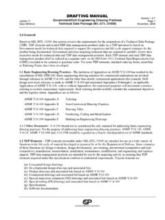
3 LINE CONVENTIONS A. The lines shown in Figure are to be used in all mechanical drawings . The corresponding AutoCAD linetype and lineweight are given next to each linetype. FIGURE : STANDARD LINESTYPES AND LINEWEIGHTS. B. The AutoCAD linetype scale (LTSCALE) for mechanical drawings plotted at a scale of 1:1 shall be set according to the table shown below: System of Measurement LTSCALE Drawing scale Decimal-inch 1:1 Metric 12 1:1 C. The linetype scale shall be modified proportionally for drawings plotted at scales other than 1:1. For example, if the Drawing scale is 1:2 for a metric Drawing , the LTSCALE shall be set to 6 (=12 x ). CENTER LINES D. The center mark size dimension variable in AutoCAD shall be .09 (2 mm). E. The center mark shall extend.
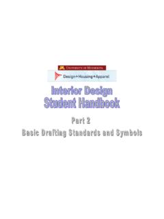
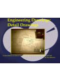
4 09 (2 mm) beyond the edges of circular features (see Figure ). Engineering Drawing & CAD Standards 2010 9 0 0 0 W e s t C o l l e g e P a r k w a y , P a l o s H i l l s , I l l i n o i s , 6 0 4 6 5 Page I-5 F. A center line representing the longitudinal axis of a cylindrical or rectangular feature shall extend .312 (8 mm) beyond the boundary of the feature (see Figure ). FIGURE : CENTERLINE EXTENSIONS. G. A center line shall not be lengthened to create the small dash when the center line is too short to show a single small dash. H. When a center line and visible or hidden line are coincident, the center line shall end before the visible line or hidden line and there shall be a .09 (2 mm) gap between the end of the center line and the beginning of the visible line (see Fig.)
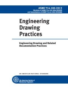
5 And ). FIGURE : CENTERLINES COINCIDENT WITH VISIBLE LINES. Engineering Drawing & CAD Standards 2010 9 0 0 0 W e s t C o l l e g e P a r k w a y , P a l o s H i l l s , I l l i n o i s , 6 0 4 6 5 Page I-6 I. If center lines are required for features arranged in a radial pattern, the center lines shall be oriented radially but shall not intersect at the center of the pattern (see Figure ). Note that the centerline bolt circle may not have the small dashes oriented at the centers of the pattern of features. FIGURE : CENTERLINES IN RADIAL PATTERNS. J. Center lines of features arranged in a rectangular pattern shall be extended so that the pattern is continuous (see Figure ). Note that the center marks for the rounded corners are extended.
6 09 (2 mm) beyond the edge of the part. FIGURE : CENTERLINES IN RECTANGULAR PATTERN. Engineering Drawing & CAD Standards 2010 9 0 0 0 W e s t C o l l e g e P a r k w a y , P a l o s H i l l s , I l l i n o i s , 6 0 4 6 5 Page I-7 K. Where center marks are used in semi-circular features, the center mark shall only extend through the circular feature edge (see Figure ). FIGURE : CENTER MARKS THROUGH SEMI-CIRCULAR FEATURES. L. Center lines may be used to indicate planes of symmetry. In such cases, the center lines shall extend .312 (8 mm) beyond the edges of the symmetrical feature (see Figure ). Center lines used as lines of symmetry do not require symmetry marks. FIGURE : CENTERLINES FOR SYMMETRICAL FEATURES. Engineering Drawing & CAD Standards 2010 9 0 0 0 W e s t C o l l e g e P a r k w a y , P a l o s H i l l s , I l l i n o i s , 6 0 4 6 5 Page II-8 II.
7 Drawing CONVENTIONS AUXILIARY VIEWS A. Auxiliary views shall be connected to the adjacent view from which they are developed by a single center line or an extension line connecting identical external edges of the part. The centerline shall go through the same feature in both views. The extension line shall have a gap between the visible edge of the part and the extension line equal to .09 (2 mm) (see Figure ). FIGURE : AUXILIARY VIEWS. B. The break line on all partial auxiliary views shall be smooth curve (see Figure ). C. Hidden lines shall be omitted on features when they appear foreshortened in orthographic views. PARTIAL VIEWS D. The break line on all partial views shall be created with a smooth curve (see Fig. ). SECTION VIEWS E.
8 The break line on all broken-out section views shall be created with a smooth curve (See Fig. ). F. The plotted arrowhead size on the cutting-plane line shall be .25 (6 mm), two times (2x) the size of the dimension arrow. G. Cutting-plane lines shall be drawn with thick phantom lines (lineweight = mm) (See Fig. ). Engineering Drawing & CAD Standards 2010 9 0 0 0 W e s t C o l l e g e P a r k w a y , P a l o s H i l l s , I l l i n o i s , 6 0 4 6 5 Page II-9 H. When a cutting-plane line is coincident with a visible, hidden, or center line, the cutting-plane line shall take precedence. I. The cutting-plane line shall extend .50 (12 mm) from the edge of the object and extend at right angles .50 (12 mm) from the extension (see Fig.)
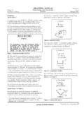
9 FIGURE : CUTTING PLANE LINES. CONVENTIONAL BREAKS J. Solid cylinders may be broken into shorter segments in a Drawing . When the solid cylinder is broken, the ends shall be shown with a conventional shaft break. The dimensions for Drawing the shaft break are shown in Fig. FIGURE : SHAFT BREAK CONSTRUCTION. J. The dimension for the overall length of the broken cylinder shall be underlined to clearly indicate that it is not drawn to scale. Engineering Drawing & CAD Standards 2010 9 0 0 0 W e s t C o l l e g e P a r k w a y , P a l o s H i l l s , I l l i n o i s , 6 0 4 6 5 Page III-10 DEVELOPMENTS J. Developed views shall show quadrants with thin solid lines. K. Sheet metal developments shall show the center line of the bends with centerlines which extend beyond the edges of the object.
10 312 (8 mm). III. DIMENSION CONVENTIONS DIMENSION APPEARANCE A. There shall be no gap between extension lines and center lines. B. drawings in decimal-inch units shall use the ROMANS AutoCAD font for all Drawing text. Metric drawings shall use the ISOCP AutoCAD font. C. The plotted size of text (including dimensions) shall be .125 (3 mm). All tolerances shall be drawn at full text height. D. All Drawing text shall have a thin lineweight (lineweight = mm). E. Dimensions and Drawing notes shall specify decimal numbers and not fractions. All fractions shall be converted to decimals with the appropriate decimal places according to the tolerance specifications. F. If an extension line crosses an arrowhead the extension line shall be broken around the arrowhead.