Transcription of Structural Detailing Standards - Caltrans
1 Structural Detailing Standards June 2005 Customary Units Table of Contents 1. General .. 1 2. Paper Sizes .. 1 3. Drawing Sizes .. 2 4. Scales .. 2 5. Units .. 4 6. Writing Conventions .. 4 7. Customary Units Conversions .. 4 8. Concrete Strength .. 6 9. Reinforcement .. 7 10. Structural 10 11. Survey Information .. 11 12. Cross Slopes .. 11 13. Side Slopes .. 11 14. Cross Section Intervals .. 12 15. Contour Intervals .. 12 16. Footings .. 13 17. Piles .. 13 18. Bolted Connection ( Structural Steel Joints) .. 14 19. Bearing Pads and Joint Seal Assemblies .. 15 20. Prestressed Concrete .. 15 21. Vertical Clearance .. 15 22.
2 Examples of Notes .. 16 23. References .. 18 Structural Detailing Standards 1 1 - General A decision document (Ref. 1) and a transition plan (Ref. 2) were developed and approved to convert from Metric units to English units ( Customary units). Customary units ( inch-pound or pound-inch units) are defined by the National Institute of Standards and Technology (NIST). (Web address: ) Users should become familiar with NIST and other equally reliable sources to obtain knowledge and skills exceeding the scope of this Structural Detailing Standards . Items that need to adapt the Customary units should be sent to the chair person of the Structure technical committee that addresses those specific items or to John Roccanova, the Department s Metric to Customary units Coor dinator in the Office of Planning and Design.
3 Division of engineering Services Office of Office Engineer (DES OOE) will convert the Standard Specifications, Standard Plans, Standard Special Provi sions and the BEES (Basic engineering Estimating System) to Custom ary units before the first Customary units project goes out for advertise ment. 2 - Paper Sizes Customary units drawings may be made on any size paper. The Division of engineering Services will continue to use the 24" x 36" paper for structure plans. When sending the file to DES OOE, the files will be based on the 24" x 36" paper size. Structural Detailing Standards 2 3 - Drawing Sizes The Division of engineering Services will use the 24" x 36" paper with a 21" x 33 " + drawing size for structure plans.
4 Reduced set drawings will still be based on a 50% reduction. 4 - Scales US Customary drawing scales are expressed in inches to feet ratios. Metric drawing scales are expressed in non-dimensional ratios. Project Development is proposing the following for Profile Sheets (Reference 2) A) Rural Sections in hilly or mountainous terrain 1"= 100' horizontal, 1" = 10'-0" vertical B) Rural or urban with gentle rolling terrain 1"= 50' horizontal, 1" = 5'-0" vertical C) Rural or urban with level terrain 1" = 20'-0" horizontal, 1" = 2'-0" vertical, Project Development is proposing the following for Cross Sections (Reference 2) A) Rural: 1" = 10'-0" B) Urban.
5 1" = 5'-0" Customary Units 3 The Office of Structure Design, Office of Structure Design Services & Earth quake engineering , proposes the use of the following scales. US Customary Scale 1' = 1'-0" (Full Size) 6" = 1'-0" (Half Size) 3" = 1'-0" 1 1/2" = 1'-0" 1" = 1'-0" 3/4" = 1'-0" 1/2" = 1'-0" 3/8" = 1'-0" 1/4" = 1'-0" 3/16" = 1'-0" 1/8" = 1'-0" 3/32" = 1'-0" 1/16" = 1'-0" 1" = 10' 1" = 20' 1" = 30' 1" = 40' 1" = 50' 1" = 80' 1" = 100' 1" = 200' 1" = 250' 1" = 400' 1" = 500' 1" = 1000' Close Metric Scale 1:1 (Full Size) 1:2 (Half Size) 1:4 1:8 1:10 1:20 1:25 1:30 1:50 1:80 1:100 1:125 1:200 1:100 1:250 1:400 1:500 1:600 1:1000 1:1200 1:2000 1:3000 1:5000 1:6000 1:10000 Structural Detailing Standards 4 5 - Units Plans will contain Customary units only.
6 The preferred Customary units (base units) are the foot (') and inch ("). 6 - Writing Conventions For writing conventions for Customary units and numbers see Metric Units to Customary Units General Primer [California Department of Transportation] - February 1, 2005 . 7 - Customary Units Conversions Class Multiply: By: To Get Area m2 ha(10,000 m2) m2 m2 km2 x 10-4 acre acre ft2 yd2 mi2 Length * m mm m km m x 10-2 ft in mils mi Customary Units 5 Class Multiply: By: To Get Volume m3 L** ML** m3 m3 x 10-4 ft3 gal fl oz yd3 acre ft Mass gkg tonne (1000kg) kgtonne (1000kg) x 10-3 oz lb kip (1000 lb) short ton (2000 lb) short ton (2000 lb) Force N kN kN lb kip ton Density kg/m3 kg/m3 lb/yd3 lb/ft3 Pressure PaMPa (N/mm2) Pa kPa kPa x 10-4 psi ksi psf psf ksf Velocity m/s m/s km/h ft/s mi/h mi/h Light lux (lx) (lumen/m2) footcandle (lumen/ft2) Temperature oC t o F = t o C (9/5) + 32 oF* The actual conversion factor is for the Survey Foot, where the factor is equal to 3937.
7 1200 ** L is used so as not to be confused with the numeral 1 . Structural Detailing Standards 6 8 - Concrete Strength Concrete fc ' Use 25 MPa 3,600 psi 28 MPa 4,000 psi * 35 MPa 5,000 psi 42 MPa 6,000 psi * Specify concrete strengths in 500 psi increments above 4000 psi. Note: The standard design strength is 3600 psi. Customary Units 7 9 - Reinforcement Customary Units (Imperial) reinforcement will be used in place of metric reinforcement. Imperial Reinforcing Bars: Use ASTM A706 Grade 60 Bar Sizes Soft Metric* and Inch Bar Designation No. Nominal Diameter Nominal Area Metric* Imperial mm in.
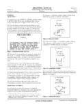
8 Mm2 10 3 71 13 4 129 16 5 199 19 6 284 22 7 387 25 8 510 29 9 645 32 10 819 36 11 1006 43 14 1452 57 18 2581 * Metric Bar Designation number approximates the number of millimeters of the nominal diameter of the bar. Specify bar length to the nearest half inch for embedment and hook dimen sions, and two inches for length. Spacing of reinforcement should be shown to the nearest quarter inch. Spac ing of reinforcement is assumed to be in inches unless otherwise noted. With this assumption, the inch symbol is not required. Structural Detailing Standards 8 Standard Hook Details In accordance with ACI 318-02 Note: All dimensions are in inches All grades.
9 D = finished inside bend diameter D = 6db for #3 through #8 = nominal bar diameter D = 8db for #9, #10 and #11 db D = 10db for #14 and #18 Recommended End Hooks, All Grades*Bar Size D 180o Hooks 90o Hooks A J A #3 2 5" 3 6 #4 3 6" 4 8 #5 3 7" 5 " 10" #6 4 8" 6 " 1'-0" #7 5 10" 7 " 1'-3" #8 6 11" 8 " 1'-5" #9 9 1'-3" 1'-0" 1'-7" #10 10 1'-5" 1'-1 " 1'-10" #11 12 1'-7" 1'-3" 2'-0" #14 18 2'-3" 1'-10" 2'-7" #18 24 3'-1" 2'-5" 3'-6" For information only Customary Units 9 = = Stirrup/Tie Hook Details In accordance with ACI 318-02 Note: All dimensions are in inches All grades: D = finished inside bend diameter Stirrup Hooks (Tie Bends Similar)Bar Size D 90o Hooks 135o Hooks A or G A or G H #3 1 " 4" 4" 2 " #4 2" 4 " 4 " 3" #5 2 " 6" 5 " 3 " #6 4 " 1'-0" 7 " 4 " #7 5 " 1'-2" 9" 5 " #8 6" 1'-4" 10 " 6" D = finished inside bend diameter H dimension is approximate For Seismic hook, dimension length on detail.
10 Structural Detailing Standards 10 Comparison of Deformed Bar Designation Numbers, Nominal Weights [Masses] and Nominal DimensionsBar Designation Number A Nominal Weight (lb/ft) Nominal Dimensions B Diameter (in.) Cross-Sectional Area ( ) Perimeter (in.) 3 4 5 6 7 8 9 10 11 14 18 A Bar numbers are based on the number of eighth of an inch included in the nominal diameter of the bars. B The nominal dimensions of a deformed bar are equivalent to those of a plain round bar having the same weight per foot as the deformed bar.