Transcription of Ep1 - Sparling Instruments
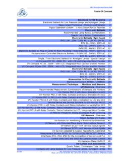
1 TM Original Issue Date: March 2002 Revision 160323 FM657 FM656 FM626 Sanitary FM626 FM627 TABLE O F CONTENTS Page SECTION 1 - GENERAL .. 1 Measuring System .. 1 Operating Principal .. 1 Application to Magnetic Flow Measurement .. 1 Interference .. 2 System Operation .. 3 Construction .. 4 Specifications .. 5 Interchangeability .. 7 Flow Rates, Dimensions & Weight .. 7 SECTION 2 - PRE-INSTALLATION .. 10 Receiving and Inspection .. 10 Storage .. 10 Return of Equipment .. 10 SECTION 3 - INSTALLATION .. 11 Application Considerations .. 11 Site Selection .. 11 Rotating the Transmitter Display .. 12 Removable Electrodes .. 13 Hot-Tap Removable Electrodes .. 13 Pipe Connections .. 15 Special Mounting Bolts & Gaskets .. 16 Grounding .. 20 Electrical Connections .. 21 Remote Mounted Transmitter .. 24 Lightening Protection.
2 28 SECTION 4 - START-UP .. 28 Start-Up Procedure .. 28 SECTION 5 - CALIBRATION .. 28 Calibration .. 28 SECTION 6 - MAINTENANCE .. 29 SECTION 7 - TROUBLESHOOTING .. 29 General .. 29 Troubleshooting Chart .. 29 Electronics Self Test .. 31 Electronics Module Replacement .. 31 Sensor Testing .. 32 Coil Continuity Testing .. 33 Coil Insulation Test .. 33 Page Electrode Circuit Insulation Test .. 33 SECTION 8 REPLACEMENT PARTS LIST .. 34 APPENDIX 1- PROGRAMMING .. 35 General .. 35 Entering Data .. 35 Batching Modes .. 36 Show Meter Data .. 36 Password Entry .. 36 Rescale Rate .. 37 Select Rate Units .. 37 Set Full Scale .. 38 Select Rate as % of Full Scale .. 38 Rescale Total .. 38 Lockout .. 38 Alarms .. 39 Count Direction .. 39 Select Total Units .. 39 Set Registration.
3 40 Reset Totalizer .. 40 Set Outputs .. 40 Select Pulse Width .. 40 Backlight .. 41 Set Flow Direction .. 41 Empty Pipe Detection .. 41 Protocol .. 41 Damping Adjustments .. 42 Display Damping .. 42 Current Damping .. 42 Low Flow Cutoff .. 42 Exit Programming .. 42 Change Password .. 42 Change Tag .. 43 Diagnostics .. 43 Check HART Transmission .. 43 Check Coil Current .. 43 Check Current Loop .. 44 Calibrate 4- 20mA Loop .. 44 Set Frequency .. 44 Simulate 75% FS .. 45 Simulator Check .. 45 IDS-626/627/656/657 Page i TABLE O F CONTENTS cont'd. APPENDI X 2 Batch Programming Page Page and Operation .. 46 General .. 46 Programming .. 46 Lockout .. 46 Rescale Total .. 47 Batch On/Off .. 47 Alarms .. 47 Count Direction .. 47 Select Total Units .. 48 User Defined Totalizer Units.
4 48 Conversion Factor .. 48 Description of Operating .. 49 APPENDIX 3 - Communication .. 50 RS232 Sparling Protocol .. 50 RS485 .. 51 FIGURES Measuring Principal .. 1 Block Diagram .. 3 Dimensions .. 8 Full Pipe Required .. 11 Changing th e Rotatable Display .. 12 Hot Tap Electrode .. 13 Removing the Electrode .. 14 FM626 Gasket Installation .. 18 FM626 Sensor Position .. 18 FM656 Gasket Installation .. 19 FM656 Sensor Position .. 19 Grounding .. 20 Conduit Connections .. 21 Electrical Connections I/O PCB .. 22 Installing Diode Across Inductive Loads .. 23 TigermagEP Remote Display .. 24 FIGURES cont'd. TigermagEP Remote Conduit Connections .. 24 TigermagEP Standard Motherboard .. 25 Remote Mounted Transmitter .. 27 Power Supply Voltage Ratings .. 28 Access to Electronics.
5 31 Removing the Electronics Module .. 31 Aligning Electronics Module with Card Guides .. 32 Replacing the E2 PROM Chip .. 32 Coil Resistance Testing .. 33 Coil Insulation Testing .. 33 Electrode Circuit Insulation Test .. 33 TigermagEP Display .. 35 Main Program .. 36 Rescale Rate Flow Chart .. 37 Rescale Total Flow Chart .. 38 Set Outputs Flow Chart .. 40 Connecting HART Communicator .. 41 Set Damping Flow Chart .. 42 Change Tag .. 43 Diagnostics Flow Chart .. 43 Simulate Mode .. 45 Enclosure fo r TigermagEP with Batching .. 46 Rescale Rate w/Batcher Flowchart .. 47 TABLES Flow Rates .. 7 .. 7 .. 9 Material .. 15 .. 16 , Flange & BoltSpecifications .. 17 Page ii TigermagEP Modbus RTU ..52 General Measuring System The Sparling TigermagEPTM Model FM-626, FM627, FM-656 and FM-657 flowmeters are obstructionless devices fo r monitoring th e volumetric flo w of conductive liquids in ful l closed pipes.
6 The flowmeter consists of a sensor (wafer or flanged) with a nonmagnetic liner, sensing electrodes and a measuring transmitter. Operation is based on Faraday s Law of Mag- netic Induction. An electrically conductive liquid flowing through a magnetic field induces a volt- Operating Principle age which is perpendicular to this field and to the direction of the flow. This voltage is proportional to the average flow velocity. See Figure The mathematical formula describing Faraday s law reads: E = B x L x V E = Induced voltage B = Magnetic field intensity (flux density) L = Distance between the electrodes (pipe diameter) V = Average flow velocity of liquid Application to Magnetic Flow Measurement Measuring Principle Figure In a magnetic flowmeter th e liquid acts as a moving conductor as it flows through th e pipe. The induced voltage (E) in the liquid is measured by two sensing electrodes mounted opposite each other in the meter sensing head.
7 The length of th e conductor is equal to the distance between sensing electrodes and also the internal diameter (D) of the pipe. The flux density is proportional to the coil current (I) , times a constant (k). The above formula can be restated as follows: E = I x k x D x V flow 0 V = cross sectional area = A 0 x I x 4 x k E = D2 Note that if I is held constant, E is proportional to 0 or the induced voltage is directly proportional to the average flow rate (V). IDS-626/627/656/657 Page 1 Interference Electrochemical Interference The signal voltage is measured by two electrodes. Galvanic elements form on the surface areas between the ion-conducting liquid and the metal electrodes. The polarization voltages which result are dependent on temperature, pressure, and the chemical composition of the electrodes and liquid. These are direct voltages which cannot be predicted and which can be different at each electrode.
8 The signal voltage must be separated from the interference direct voltage. Proper grounding eliminates these unpredictable voltages from interfering with the signal voltage. Induction Interference (Quadrature) Electrode cables connect the electrodes with the meter electronics. Because these cables must run within the magnetic field, a voltage is induced which is proportional to the rate of change of the magnetic field strength. The meter design minimizes th e length of conductor within the magnetic field in order to keep the value of this interference as low as possible. Other Interference Voltages Pipes and the liquids within them are often used as a conductor fo r electrical grounding. This creates a voltage potential between electrodes which can be high relative to the signal voltage. Proper grounding of the flowmeter to the liquid is necessary to achieve correct meter operation.
9 Grounding rings should be installed if the flowing medium has a voltage potential, if piping is nonconductive (plastic or lined) or if conductivity is below 20 micromhos/cm. See Section - Grounding. Page 2 TigermagEP System Operation The Sparling TigermagEP uses the autozeroing, bipolar, pulsed-DC measuring technique. The circuitry (Fig. ) energizes the coil with 300 mA typical current at a frequency of up to 100 Hz. The signal generated at the electrodes is measured near the end of each measuring cycle to eliminate the capacitive effects of coatings. The Hi-Z (1012 ) input impedance eliminates the resistive effects of electrode coatings. The field current alternates to a positive and negative state and th e two measured signals are averaged to eliminate the effect of a zero offset-this is the auto-zeroing feature.
10 1. Measuring Sensor 6. Sample and Hold 11. Adjustable Empty Pipe 14. LCD Display with Hall- Effect 2. Electrode Cable PCB 3. Input Amplifier 7. Voltage to Frequency Converter 8. Nonvolatile E2 PROM Detection (in software) 12. Watchdog Timer Switches 15. Optocouplers 4. Summing Point 9. Coil Current Multiplexer 13. Microcontroller 16. Frequency to Current Ct 5. Autozero Circuit 10. Built-in Simulator 17. Power Supply Section Block Diagram Figure IDS-626/627/656/657 Page 3 Construction Sensor The FM626 is a wafer style meter. It is available with either a ceramic or optional Tefzel liner. The Tefzel liner is rotamolded onto a stainless steel sensor tube. Both liners are press-fit into a carbon steel housing. The FM627 is a wafer style meter. The flow sensor housing is made of steel with a polyurethane liner.