Transcription of EST Fire & Life Safety Intelligent Initiating Devices
1 GE EST Fire & Life Safety Security Intelligent Initiating Devices Overview Fast Stable Communication - On-board intelligence means less information needs to be sent between the detector and the loop The Signature Series Model SIGA-PS Intelligent Photoelectric Smoke controller. Other than regular supervisory polling response, the Detector gathers analog information from its smoke sensing ele- detector only needs to communicate with the loop controller when ment and converts it into digital signals. The detector's on-board it has something new to report. microprocessor measures and analyzes these signals.
2 It compares the information to historical readings and time patterns to make an alarm decision. Digital filters remove signal patterns that are not typical of fires. Unwanted alarms are virtually eliminated. Standard Features The microprocessor in each detector provides four additional benefits Integral microprocessor - Self-diagnostics and History Log, Automatic Device Mapping, Non-volatile memory Stand-alone Operation and Fast, Stable Communication. Automatic mapping device Self-diagnostics and History Log - Each Signature Series detec- tor constantly runs self-checks to provide important maintenance Electronic addressing information.
3 The results of the self-check are automatically updated Environmental compensation and permanently stored in the detector's non-volatile memory Intelligent detector Automatic Device Mapping - The loop controller learns where each Wide to sensitivity range device's serial number address is installed relative to other Devices on the circuit. The mapping feature provides supervision of each Twenty pre-alarm sensitivity values, set in 5% increments device's installed location to prevent a detector from being rein- Identification of dirty or defective detectors stalled (after cleaning etc.)
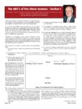
4 In a different location from where it was originally. Automatic day/night sensitivity adjustment Stand-alone Operation - A decentralized alarm decision by the Twin RED/GREEN status LEDs detector is guaranteed. On-board intelligence permits the detector Standard, relay, fault isolator, and audible mounting bases to operate in stand-alone mode. If loop controller CPU communica- tions fail for more than four seconds, all Devices on that circuit go Designed and manufactured to ISO 9001 standards into stand-alone mode. The circuit acts like a conventional alarm receiving circuit. Intelligent Photoelectric Smoke Detector SIGA-PS.
5 S. CHINA. Application Notes Available Data Sheet 85001-0269 Issue 6. Not to be used for installation purposes. Page of 4. Installation Accessories Signature Series detectors mount to North American 1-gang boxes, All detector mounting bases have wiring terminals that are acces- 3-1/2 inch or 4 inch octagon boxes, and to 4 inch square electrical sible from the room-side after mounting the base to the electrical boxes 1-1/2 inches (38 mm) deep. They mount to European BESA box. The bases mount to North American 1-gang boxes and to 3 . and 1-gang boxes with mm fixing centers. inch or 4 inch octagon boxes, 1 inches (38 mm) deep.
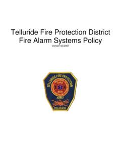
6 They also mount to European BESA and 1-gang boxes with mm fixing centers. The SIGA-SB4, SIGA-RB4, and SIGA-IB4 mount to North American 4 inch sq. electrical boxes in addition to the above boxes. They include the SIGA-TS4 Trim Skirt which is used to cover the mounting ears on the base. The SIGA-AB4G mounts to a 4 sqare box only. SIGA-AB4G SIGA-SB SIGA-IB SIGA-RB SIGA-LED. Audible Base Standard Base Isolator Base Relay Base Remote LED. Standard Base SIGA-SB, SIGA-SB4 - This is the basic mounting base for GE Security Signature Series detectors. The SIGA-LED. Remote LED is supported by the Standard Base.
7 Relay Base SIGA-RB, SIGA-RB4 - This base includes a relay. Nor- mally open or closed operation is selected during installation. The dry contact is rated for 1 amp (pilot duty) @ 30 Vdc. The relay's position is supervised to avoid accidentally jarring it out of position. The SIGA- RB can be operated as a control relay if programmed to do so at the control panel (EST3 only). The relay base does not support the SIGA-LED Remote LED. Testing & Maintenance Audible Base SIGA-AB4G - This base is designed for use where Each detector automatically identifies when it is dirty or defective localized or group alarm signaling is required.
8 When the detector and causes a dirty detector message. The detector's sensitiv- senses an alarm condition, the audible base emits a local alarm ity measurement can also be transmitted to the loop controller. A signal. The optional SIGA-CRR Polarity Reversal Relay can be used for sensitivity report can be printed to satisfy NFPA sensitivity measure- sounding to other audible bases on the same 24 Vdc circuit. ments which must be conducted at the end of the first year and every two years thereafter. Relay and Audible Bases operate as follows: - at system power-up or reset, the relay is de-energized The user-friendly maintenance program shows the current state - when a detector is installed in the base with the power of each detector and other pertinent messages.
9 Single detectors on, the relay energizes for four seconds, then de-energizes may be turned off temporarily from the control panel. Availability of maintenance features is dependent on the fire alarm system used. - when a detector is removed from a base with the power on, Scheduled maintenance (Regular or Selected) for proper detector the relay is de-energized operation should be planned to meet the requirements of the Au- - when the detector enters the alarm state, the relay is energized. thority Having Jurisdiction (AHJ). Refer to current NFPA 72 and ULC Isolator Base SIGA-IB, SIGA-IB4 - This base includes a built-in line CAN/ULC 536 standards.
10 Fault isolator for use on Class A circuits. A detector must be installed for it to operate. The isolator base does not support the SIGA-LED. Remote LED. Compatibility The isolator operates as follows: The SIGA-PS detectors are compatible only with the Signature Loop - a short on the line causes all isolators to open within 23 msec Controller. - at 10 msec intervals, beginning on one side of the Class A circuit nearest the loop controller, the isolators close to provide the next isolator down the line with power - when the isolator next to the short closes, reopens within 10 msec.