Transcription of EVALUATION OF THE DESIGN LENGTH OF …
1 EVALUATION OF THE DESIGN LENGTH OF VERTICAL geothermal BOREHOLES using annual SIMULATIONS combined WITH GENOPT Mohammadamin Ahmadfard, Michel Bernier, Micha l Kummert D partement de g nie m canique Polytechnique Montr al Software tools to determine the DESIGN LENGTH of vertical geothermal boreholes typically use a limited set of averaged ground thermal loads and are decoupled from building simulations. In the present study, multi- annual building hourly loads are used to determine the required borehole lengths. This is accomplished within TRNSYS using GenOpt combined with the duct ground heat storage (DST) model for bore fields. INTRODUCTION The determination of the required total borehole LENGTH in a bore field is an important step in the DESIGN of vertical ground heat exchangers (GHE) used in ground-source heat pump (GSHP) systems.
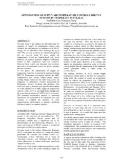
2 Undersized GHE may lead to system malfunction due to return fluid temperatures that may be outside the operating limits of the heat pumps. Oversized heat exchangers have high installation costs that may reduce the economic feasibility of GSHP systems. Figure 1 illustrates schematically a typical GSHP system. It consists of eight boreholes and five heat pumps connected in parallel. Piping heat losses between the boreholes and the heat pumps are usually assumed to be negligible. Thus, the inlet temperature to the heat pumps, , , is equal to the outlet temperature from the bore field . Heat pumps can operate with , as low as 7 C in heating and as high as 45 C in cooling. However, most designers use a safety margin and try to limit , to a value of 0 C in heating and 35 C in cooling modes.
3 Boreholes are typically connected in parallel and the inlet temperature to all boreholes, , is equal to the outlet temperature from the internal heat pump fluid loop, , . The ground thermal conductivity, , thermal diffusivity, , and the undisturbed ground temperature, , are usually evaluated (or estimated in the case of ) from a thermal response test (TRT) performed prior to the determination of the DESIGN LENGTH . The borehole thermal resistance (from the fluid to the borehole wall), , can also be estimated from a TRT test or calculated from borehole heat transfer theory (Bennet et al., 1987). Figure 1: Schematic representation of a typical GSHP system As shown in Figure 1, the bore field geometry is characterized by the number of boreholes, , the borehole LENGTH , , the borehole spacing, , and the buried depth of the boreholes.
4 Each borehole has a radius (not to be confused with , the borehole thermal resistance). As shown in section A-A, each borehole has two pipes with a radius and a center-to-center distance equal to . For typical boreholes, varies from 50 to 150 m. For such long boreholes, the value of has minimal effects on borehole heat transfer. In this work, it is assumed that = 1 m and it is not considered to be a factor to determine the DESIGN LENGTH . Designing a GHE consists in finding the optimum combination of , and such that the inlet temperature to the heat pumps doesn t go below the minimum value of or above the maximum value of . In this work, the optimum combination is the one leading to the smallest overall LENGTH (= ). In the first part of the paper, the basic DESIGN methodologies used in typical software tools are examined and categorized into five levels of increasing complexity.
5 Then, the DST model and GenOpt are briefly reviewed. This is followed by the proposed methodology to obtain the optimum DESIGN LENGTH . The objective function involves the LENGTH and number of boreholes and and are considered as constraints. Contrary to most sizing methods, the heat pump HBDTinToutTgkgg AAHeat pumpA-APipeGroutSoilFluid loopPumpTin,hpTout,hp(R )bBTout,hp2rb2rpdP Coefficient of Performance (COP) is considered variable and so the ground loads are determined iteratively. Finally, the proposed methodology is applied and compared to other DESIGN software tools in three test cases. REVIEW OF DESIGN METHODOLOGIES Spitler and Bernier (2016) categorized GHE sizing methodologies into five levels (0 to 4) of increasing complexity. The proposed methodology fits into the level 4 category.
6 These various levels will now be described with an emphasis on level 4. Level 0 Rules-of-Thumb Rules-of-thumb relate the LENGTH of GHEs to the largest heating or cooling loads of the building or to the installed heat pump capacity. One popular rule-of-thumb in North America is to determine the LENGTH based on the simple formula: 150 feet of bore per ton of installed capacity (13 m of bore per kW of installed capacity). In the United Kingdom, look-up tables are used to obtain the maximum power that can be extracted per unit LENGTH for various ground conditions (Department of Energy and Climate Change, 2011). For example, for = W/m-K and =12 C , the recommended maximum power extraction is 50 W/m for 1200 hours of equivalent full load operating hours.
7 The main problem with rules-of-thumb is that they only rely on peak loads and do not account for annual ground temperature increases (decreases) caused by load thermal imbalances. Level 1 Two ground load pulses In level l methods, two lengths are calculated based on peak heating and cooling loads. Kavanaugh (1991) introduced a borehole thermal resistance in the analysis as well as an approximate factor to account for borehole -to- borehole thermal interference. Furthermore, the concept of temperature limits ( and ) is introduced. Despite these improvements, level 1 methods suffer from the same problem as level 0 methods as they do not properly account for the effects of ground load thermal imbalances. Level 2 Two set of three ground load pulses The three pulse methodology (3 pulses in heating and 3 in cooling) is introduced by Kavanaugh (1995) along with the concept of temporal superposition which leads to the development of In order to keep the analysis simple, the borehole thermal resistance is assumed to be negligible and so it has been eliminated from the equation (it will be reintroduced later).
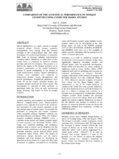
8 In this equation, is the overall borehole LENGTH (= ), is the ground thermal conductivity, is the mean fluid temperature (= [ , + , ]/2) and is the ground temperature. The temperature penalty, , accounts for the borehole -to- borehole thermal interference (Bernier et al., 2008). 1, 2, and 3 are three consecutive ground load pulses with time durations 1, 2, 3. The values of 1 , 2 and 3 are equal to 1, 1+ 2, and 1+ 2+ 3, respectively Finally, the function is the thermal response of the ground which can be evaluated using several techniques. Figure 2 shows schematically three typical heat load pulses and their durations. =1 1 ( 3 0)+( 2 1) ( 3 1 )+( 3 2) ( 3 2 ) ( + ) (1) Figure 2: Three typical ground load pulses and their durations In level 2 methods, the ground load pulses and their duration are typically assumed to be as follows: 1 is the annual amount of heat rejected (or collected) into the ground over a period 1 (typically this period is 10 years).
9 This is followed by a monthly ground load pulse 2 with a duration 2 of one month. Finally, an hourly ground peak pulse 3 with a duration of 3= 6 hours is applied. Building loads from energy simulation tools are generally not available in level 2 methods. Instead, peak building loads are calculated and the resulting peak ground loads, 3 are estimated. This estimation is based on a heat pump COP evaluated at peak conditions for , = in cooling and in heating modes. Then, the average monthly ground load during the peak month, 2, is estimated assuming a run time fraction for the heat pump during that month. Finally, the average annual ground load, 1, is estimated. This can be done using the concept of equivalent full load heating and cooling hours as described by Spitler and Bernier (2016).
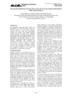
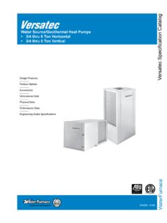
10 It is to be noted that 1 and 2 are based on assumed constant COP values because the evolution of , is unknown in level 2 methods. These calculations are performed for both heating and cooling modes giving two sets of three ground load pulses. The end result of these calculations is illustrated in Figure 3a for a case where the building is mainly in cooling mode. In this example, 1, 2, and 3 have the qg Ground loads (kW)t (days)Q1Q2Q3t1t2t3t1t2t3 following values: , , and kW. These values are used in a test case to be examined shortly. Figure 3: Typical ground loads related to level 2 sizing methods and the variation of related to these loads Eq. 1 forms the basis of the ASHRAE sizing method (ASHRAE, 2015) where is based on the analytical solution to ground heat transfer referred to as the infinite cylindrical heat source or ICS (Bernier, 2000).