Transcription of Exit Detector - cerber.pro
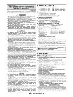
1 ExitDetectorINSTALLATION INSTRUCTIONST echnical SpecificationsDetector typePassive InfraredFilter technologyDigital Signal Processing ( ) Detector lensCurtain type Fresnel lensDetection rangeOne hand: 3m (10 ft.) / Whole body: 6m (20 ft.)Power consumption 12-28 volts DC, 50 mAPiezo buzzer90 dB at 28V, 5-28 volts DC,20 mA. (XL & XL2 only)Main relay contacts SPDT,1A max. at 30 volts DC relay timerAdjustable, 1/2 to 60 secondsMain relay recycle timeFixed, 3/4 second offLock control 2A max at 30 volts DCTime fixed at 2 seconds (LT2 & XL2 only)Tamper , 100mA max at 30 volts DC L x W x D7-1/8"L x 1-3/4"W x 1-7/8"DIndicator lightRed/Green LEDC ertificationUL 294, CE, FCCI nstallationRefer to the illustration below for the recommendedmounting positions. When selecting an appropriatemounting position, keep in mind the potential for airdrafts or objects to be passed through gaps aroundthe door and into the detection cable entry opening into the is on theright back side, near the cover retaining screw.
2 Thereis a recess in the back of the to allow wires tobe routed from any point behind the to thecable entry , remove the cover, then remove the detectorbarrel from the back casing by rotating the barrelupward. Route the wiring into the back casing. Next,mount the back casing to the wall. Install the detectorbarrel into the back casing and connect the is a good time to modify the jumper settings ifnecessary; the jumper settings are explained on nextpage. Make sure that the barrel is free to rotate, topermit final adjustment. Replace the cover, left endfirst (the end with 2 hooks).MA1103EN-9901 1996 - 1999 KANTECH SYSTEMS Systems : 1(450) 444-2040 Fax: 1(450) 444-2029 Jumper SettingsThere are a total of 7 jumpers on the left side of the circuitboard. In default, all jumpers are JumperThis jumper selects whether or not the LED changescolour when the main relay is activated.
3 By default, theLED is enabled to follow the relay JumperThis jumper determines the relay operation: in Latch mode(the default), the relay activates for the duration of themain relay timer setting whenever someone is follow mode (jumper removed), the relay stays on onlyas long as there is activity in the detection zone, but upto a maximum time equal to the main relay timer JumperThis jumper selects between normal and high set to high sensitivity (the default), the LED isnormally red, and turns green when the main relay isactivated. This mode is recommended for exit normal sensitivity is selected, the LED is normallygreen, and turns red when the relay is activated. (Selectingnormal sensitivity allows the to be used in unsteadyenvironments).Main Relay Timer JumpersThe duration of the relay ON time (Latch mode) or themaximum main relay ON time (Follow mode), is set bythese jumpers, found on the lower left side of the circuitboard.
4 16 different times can be selected according tothe main relay timer setting table, ranging from 1/2 secondto 60 seconds. The default setting is 2 both latch and follow modes, when the main relay turnsoff again, it will stay off for 3/4 second. This is to ensurethat the access control panel does not miss brief changesof Control Relay (LT2 and XL2 only)The lock control relay is deactivated (open contact) after2 seconds on a Three JumpersJumperJumper OnJumper Off(Factory Default)LEDLED follows stays stays on forRelay follows detection, uptimer maximum of timer sensitivity,Normal sensitivity,LED normally red,LED normally greenLED green on detection. LED red on TestThe LED will flash twice quickly every second while goes through its power-up diagnostic sequence(about 40 seconds) after which the is ready tooperate normally.
5 If trouble is detected at any time, theLED will begin to flash rapidly 4 times per second. If is upset by a strong power fluctuation, it will resumenormal operation after a 10 second self Pattern AdjustmentOnce the is installed and the cover replaced, thespan and target direction of the detection pattern is setby gently turning the louver direction screws, located justbelow the Detector lens on the barrel. As the adjustmentrange is about 45 , you must be careful not to turn thelouvers too far; stop turning when resistance is felt. Theslots on the louver adjusting screws indicate the positionof the louver and serve as an adjustment guide. To adjustthe detection zone toward or away from the door, simplyrotate the Detector barrel as required. When the mounted directly above the door, it is recommendedto direct the detection area away from the door.
6 Rotatethe barrel slightly away from the door, such that the loweredge of the Detector lens is about 1/4" above the edge ofthe case. Check that the detection pattern is adequateby walk testing. Watch the LED for position you are satisfied with the detection pattern, removethe cover and tighten the barrel locking screw on theright side of the barrel, and replace the This Detector provides fast detection and has not been designed to be used inintrusion detection applications. This Detector is designed to detect an individual approaching adoor. Normally, upon receiving the Detector information, the system supervising the door willbypass the door condition for a certain time to permit the exit without causing an alarm. Thisdetector is designed to be used on free exit doors.
7 It has not been designed to unlock and associated devices are generally governed by regulatory bodies and should alwaysbe installed according to local regulations. In most instances there are strict limitations to installingthis type of device on doors used to exit . Be sure to check with local authorities for regulationsbefore using any such device complies with Part 15 of the FCC Rules. Operation is sub-ject to the following two conditions: (1) This device may not causeharmful interference, and (2) this device must accept any interferencereceived, including interference that may cause undesired or modifications not expressly approved by Kantech couldvoid the user s authority to use this No. , no piezo, , no piezo with 2 with 2 relaysJumper Relay timer SettingsTime(seconds)JumperMade in Canada