Transcription of Experience with Artificial Leaks and Dye Ingress Container ...
1 Experience with Artificial Leaks and Dye Ingress Container Closure integrity testing (CCIT)Klaus Wuchner, PDMS Large Molecule Analytical Methods Development, Schaffhausen, SwitzerlandAAPSNBC, Boston, May 17, 2016 DISCLAIMERThe perspectives and opinions in this talk are those of the industry started to develop sterile packaging solutions cans have been available since 1880s1996: 10 000 000 000 aseptic food packages were distributedPackaging should avoid microbial spoilage or infiltration of pathogens into products throughout the product shelf life1970 Septicemia problem Approx. 200 patients in hospitals showed septicemia(blood poisoning) with 20% mortality Hospitals used IV products from Abbott Labs Screw cap closure for infusion bottles with new elastomer liner Viable strains got into interior of screw-cap closures after autoclave step during production Cooling closures drew moisture through the thread interstices2 CCI addresses the maintenance of integrity to prevent microbiological Ingress in sterile product packaging until the time of use (product opening)Critical leak Void, gap, crack, hole, porosity or breach in a Container closure system allowing the passage of microorganisms Main factor that affects critical leak size is whether or not the micro-leak is filled with liquid.
2 Microorganisms penetrate a liquid filled defect by motility or pressure differentials Still a lot of controversy discussions about the leak size at which the sterility may be jeopardized 10 m for fused silica capillary (Burrel, 2000) 50 m for channel Leaks (Yam, K. 1995) m Glass Micro-Pipettes (Kirsch, 1997) 4 m pinhole in steel plate (Morrical, 2007) 20 m OD Wire (Morrical, 2007) 3 Artificial Leaks -Purpose of Artificial Leaks Used to assess sensitivity and performance of a technique, , experimentally define limit between non-leaking and leaking CCS (CCIT method development) Correlation of pCCITto microbial Ingress (mCCCI) Assay validation purposes SST/assay controls4 Types of Artificial Leaks Most commonly used methods of creating Leaks : Laser drilling into the body of the Container Laser drilling into a metal plate or tubing that is integrated to a CCS Micron-wires inserted at the interface between the closure and Container Micropipettes (glass) inserted into the stopper or glued into an Artificial hole of the Container Capillaries (fused silica, nickel, glass) or needles (steel) inserted into the stopper or glued into an Artificial hole of the container5 Laser drilled holes (orifices)AdvantagesDisadvantages 1-2 m in Container ( , glassvial) m in thin steel plates Many materials can be used, , glass Container , steel plates/tubings Leaks are closer to real world defects (no defined geometry) Need to be prepared in specialized labs and are expensive The size of laser-drilled void needs to be calibrated Positive controls cannot be prepared directly on the product (product filled containers cannot be used for laser drilling)
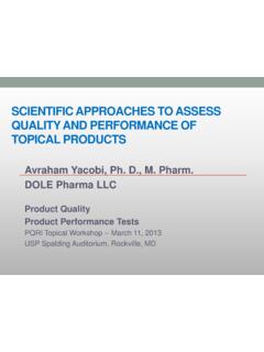
3 Non-negligible risk of alteration of void post manufacture and/or calibration, prone to plugging during handling, shipment, storage: , small holes can clog easily (silicone oil in siliconizedsyringes,due to micro-particles/fat from finger)6 Laser drilled holes (orifice)7 Laser-drilledhole in glass vial wallLaser drilled hole in stainless steel capillary which is glued into rubber stopper of a vialWires8 AdvantagesDisadvantages 10 m (OD) wiresin different materials available Create micro-channels between elastomeric closure and Container , , similar to hair/foreign object between Container and rubber closure ( , lip of vial) mimicpotential real world gap (undefined path) Wide range of " Leaks can be prepared Low cost Actual size depends on many parameters (diameterof wire, elasticity of rubber, press fit forces) Handling of the micron wires can be difficult and the size of the void needs to be calibrated Wire need to be inspected to ensure that they were not broken during sealing process The holes can close up over time depending on the relaxation of the materials ( , stopper)Wires9 Nieto et al.
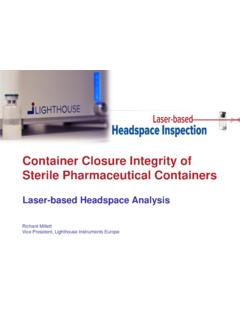
4 , PDA Journal of Pharmaceutical Science and Technology, 2016 Glass pipettes10 AdvantagesDisadvantages m (nominal internal diameter, tip) Consistent pinhole type defects Materialmatches primary packaging if glass pipettes are used Break very easily, too fragile for routine use Get larger, need to verify by microscope or flow rate measurements after sample preparation or handling(exposure to test conditions) High risk of false sensitivity after preparation of a positive control(change of tip diameter)Glass pipettes1110 m new glass pipette(approx. 50 m opening under microscope)10 mnominal glass pipette(after handling (approx. 100 m opening under microscope)Capillaries12 AdvantagesDisadvantages m internal diameter (fusedsilica) Robust, wide size range and different materials available (fused silica,glass, nickel) Easy preparation directly at the testing location Leakage rate can be fine-tuned through length of capillaries Consistent dimensions/ Leaks Due to defined dimensions, no need to calibrate each individual leak Geometry different from real world Leaks Uncertainty on actual diameter for very small , m mCapillaries -Practical Aspects1310 mCapillary gluedOnly defined leakage10 mCapillary not gluedUndefined leakageCapillaries Practical Aspects14 Placement of capillary may be difficult and high risk for damage or inadvertent closure by glue or handling.)
5 Dimensions of capillary need to be controlled irrespective of product fill volume Length of capillary varies as a function of fill volume (stopper position) Difficult to glue, only at outer part of stopper Through syringe rubber stopperOptimized Stopper Replacement Part Consistent Length of capillary for each stopper position Improved preparation of positive leakage controlsTubings Gross leaks15 Methods need to be evaluated for response to large Leaks (limitation of specific method, laser based headspace analysis can not directly detect larger Leaks because of fast equilibration of head space with environment)Other types of gross Leaks Injection needles of various internal diameters Cutting part of or piercing of rubber stopper Absence of a closure Cut mm ID gluedintorubberstopperComparisonofartifi cialleaks16 ReplicatesHe-Leak [mbar*L/s]Background X 10-10to x 10-9 Negative Leakage Control(tight empty vial) to x 10-9 Laser Drilled Holes5 m steel capillary (nominal flow effective diameter; glued into rubber stopper) X 10-4to x 10-32 m in vial glass body (nominal flow effective diameter; empty vial) to x 10-53 m in vial glass body (nominal flow effective diameter; empty vial) to x 10-45 m in vial glass body (nominal flow effective diameter.)
6 Empty vial) to x 10-4 Copper Wires10 m OD (placed between rubber stopper and vial, capped at different compression) X 10-9to x 10-730 m OD (placed between rubber stopper and vial, capped at different compression) X 10-8to x 10-4 Micro-glass Capillaries (glued into rubber stopper of vial)2, 5, 10 m tip (nominal ID) X 10-4to x 10-2 Procedural Negative Leakage Control (closed, glued fused silica capillary in rubber stopper of vial) to x 10-9 Fused Silica Capillary (glued into rubber stopper of vial)2 m (ID) x mm (L) X 10-9to x 10-85 m (ID) x mm (L) to x 10-710 m (ID) x mm (L) X 10-6to x 10-515 m (ID) x mm (L) to x 10-525 m (ID) x mm (L) X 10-4to x 10-3 Comparisonofartificialleaks17 Non leaking levels were approx. 5 x 10⁻⁹mbar*L/s (background, tight vials, procedural blanks with glued capillaries) Same very low flow rates (approx. x 10-8mbar*L/s) observed for 2 m fused silica capillaries (L:~12 mm), 92% of 10 m and 42% of 30 m wires Comparable flow rates (1-9 x 10⁻⁴mbar*L/s) for most of 5 m laser drilled holes, 17% of 30 m wires and 25 m fused silica capillaries (L:~11 mm) 10 m fused silica capillaries (L.
7 ~10-13 mm) show flow rates ( x 10-6to x 10-5mbar*L/s) lower than 2 m laser drilled holes ( x 10-5mbar*L/s) It is difficult to achieve consistent leakages using wires and even more glass micro-pipettesDye Ingress USP<1207>Dye Ingress (tracer liquid submersion test) is stated as one of the CCIT useful in any of the product life cycle phasesTracer liquid test method is a destructive approach providing an indication of leak presence and may provide a measure of relative leak liquid tracer detection relies on a combination of tracer solution wicking, tracer solution effusion, and tracer element diffusion through a liquid-filled leak path and are events that are difficult to predict or control, especially for detection of smaller Leaks . These events are influenced by numerous factors, including the package materials of construction, leak path tortuosity and topography, tracer liquid surface tension, and leak path blockage by product, extraneous debris, and air liquid tests may fail to reliably detect small Leaks due to any one of a number of factors including air locks, product, or debris in the leak path; liquid surface tension; leak path geometry; or insufficient differential pressure test conditions.
8 The same is true for microbial Ingress tests that are further subject to the inherent variability of living Ingress Industry ExperienceDye Ingress (tracer liquid submersion test) is one of the most used test method to demonstrate CCI within industry: Versatile and can be used on primary and secondary packaging in support of development, manufacturing and stability testing Detects directly relevant Leaks of concern Different dyes can be used to tailor the method Improved sensitivity when optimized vacuum/pressure cycles are used. LODvaries depending on the leak size, materials, dye concentration and challenge conditions The tracer liquid must be miscible and not chemically reactive with the product Correlation to microbial Ingress can be established using the same challenge conditions Has been seen to work well for liquids but depending on the dye it may not be suitable for lyophilized products19 Dye Ingress Test Method Execution20 Prepare positive leakage controls using drug product (with fused silica capillary of defined internal diameter and controlled length)Place positive leakage controls and samples into pressure vessel and add dye solution that all units are completely immersedChallenge with successive pressure and vacuum cyclesWash (and dry if needed) exterior surface of challenged unitsVisually inspect challenged units by comparing to positive and negative dye units to determine if discoloration (dye penetration)
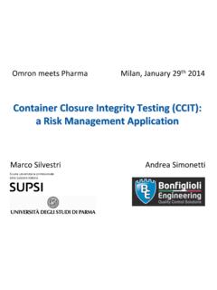
9 In case of doubt, measure UV absorbance ( for methylene blue at 670nm)DyeIngress Test Test Equipment21 Filtration of 60 Ldye solution over 20 mfilter takes >4hDye Ingress test Enhanced Equipment and Improved Method Performance MeasuresImprovements of dye Ingress procedure to improve reliability and robustness and make it QC friendly (FMEA performed): Filtration of dye solution prior each run over 1 m filter in short time Positive leakage control preparation (capillaries to be glued to reduce false positives) Challenge vessel with programmed pressure / vacuum cycles to automate method execution Optimized fixtures for samples (to avoid damage of positive controls) 22 Improvements of Dye Ingress Method23 Visual InspectionVials in Visual Inspection Station: left vial: negative dye control vial, mid vial: challenged Sample vial, right vial: positive dye control vial (blue equivalent to penetration of L dye)24 From left to right.
10 Negative dye control, negative leakage control, 4xpositive leak controls (10 m fused silica), 4xpositive leakage controls (25 m fused silica), positive dye control (blue equivalent to penetration of L dye) Dye Ingress Test Performance Characteristics Penetration of L of dye into , 1 mL filled drug product syringe can be consistently detected by visual inspection >80% of positive leakage controls with 10 m fused silica capillary of a length 11 1 mm demonstrate robustness of dye Ingress at x 10-6to x 10-5mbar*L/s (He, orifice leak to 1 m per USP) Very flexible use of optimized system, with sample sizes between 20 to a couple of hundreds units, enabling testing of vials of different size and pre-filled syringes during the same run25 Conclusions26 The leakage flow rate does not necessarily correlate to a specific hole size Referring to leak size in micrometer ( m) may suggest an absolute unit which can be compared to the size of bacteria, but this assumption is misleading!