Transcription of Experiment #1: RC Circuits
1 Experiment 1: RC Circuits 1 Experiment 1: RC Circuits Introduction In this laboratory you will examine a simple circuit consisting of only one capacitor and one resistor. By applying a constant1 voltage (also called DC or direct current) to the circuit , you will determine the capacitor discharge decay time (defined later) and compare this value to that which is expected. Alternately, by applying alternating current (AC) and varying the frequency of the current you will be able to determine the decay time in another, independent way. You will determine these expected values using formulas derived from Ohm s law, Kirchhoff s Law and the concept of complex impedance. These concepts will be detailed further in the laboratory. In addition to these new ideas you will need to recall the concepts from last week s lab.
2 Specifically you will use the multimeter and oscilloscope during this lab. Recall that the oscilloscope must be calibrated at the beginning of any Experiment in which it is used. 1 Physics Electrical circuit Definitions Any section of a circuit that is at constant voltage is called a node. An example is a piece of wire joining two or more resistors. The sum of all the currents flowing into a node must be zero since charge can neither be created nor destroyed in a circuit . circuit elements are resistors, capacitors, and inductors. One might consider wires connecting these elements to be a fourth circuit element but since idealized wires have no resistance, capacitance or inductance they are represented only by lines in a circuit diagram and do not appear in the equations relating current and voltage in Circuits .
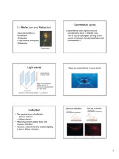
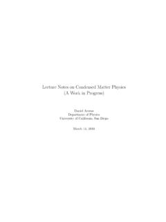
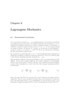
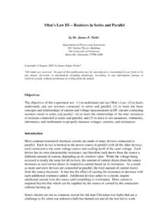
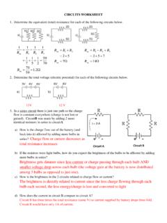
3 Figure 1 Resistors in series Figure 2 Resistors R4 and R5 in parallel 1 Applying a square wave to the circuit is not exactly applying constant voltage. However, if the period of the square wave is long enough, you will not have to worry about what happens at the end when the voltage switches from one constant voltage to another. Experiment 1: RC Circuits 2 Two circuit elements are in series if all of the current flowing through one also flows through the other. In Figure 1, all of the current flowing from the battery must also flow through the resistors R1 and R2. They are in series . In Figure 2, the current flowing through R4 does not flow through R5 (and vice versa) so that R4 and R5 are not in series . Two circuit elements are in parallel if they are connected to the same nodes.
4 R4 and R5 in Figure 2 are both connected to nodes A and B. This then also requires that the potential difference (voltage drop) across all elements connected in parallel must be the same. In more complicated Circuits you will need to generalize the notions of series and parallel. For example, in Figure 2, the equivalent resistance of R4 and R5 in parallel, 1R4 1R5 1 R4*R5R4 R5 , is in series with R3. Ohm s Law Ohm s Law states that for a resistor the current and voltage are in phase and proportional. That is: V I*R Kirchhoff s Law This law or rule states: The algebraic sum of the changes in potential encountered in a complete traversal of any closed circuit must be zero. The adjective, algebraic, is added to indicate that the sign of the potential change encountered in crossing various parts of the circuit must be accounted for.
5 For example, if two batteries are in the circuit but placed such that their potentials tend to force current in opposite directions, then the potentials must have opposite sign and the algebraic sum yields the net potential difference across both. Thus, the elements which cause a change in voltage in any circuit loop ( resistors, capacitors, inductors and batteries) will be signed and will sum to zero. Common Grounding In numerous Circuits that you will construct you will apply a voltage to an entire circuit and also measure the voltage over specific current elements. Both the applied voltage and the device which measures the voltage (typically the oscilloscope) will have one end which fixes the voltage to the common ground voltage. The common ground voltage is our standard for zero voltage and the voltage you record is measured relative to that.
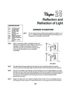
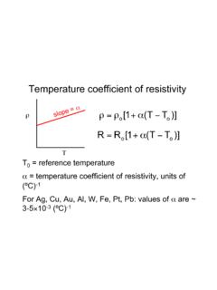
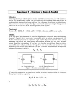
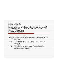
6 Below there is an example of a circuit with two resistors with AC voltage (from the function generator) applied to a resistor and capacitor in series . Figure 3 shows the circuit in which we measure the voltage of the capacitor. Notice that the ground of the function generator and the ground of the oscilloscope are next to each other in the circuit diagram. Figure 4 measures the voltage over the resistor but in this case one of the grounds is one side of the capacitor and the other is on the opposite side of the capacitor. This will measure the voltage over the resistor, but in effect removes the capacitor from the circuit because the voltage difference over the capacitor is close to zero. This is a short circuit . Experiment 1: RC Circuits 3 Figure 5 also records the voltage over the resistor.
7 However, since we have swapped the resistor and the capacitor, the grounds are at the same point in the circuit . Thus, you are measuring the voltage of the resistor in an RC circuit . Be careful when measuring the voltage of the different elements in your circuit and place the grounds in the appropriate places so that you do not short your circuit (as is the case in Figure 4). Figure 3 Voltage over the capacitor is recorded. Figure 4 Voltage over resistor is measured while circuit is shorted . Figure 5 Voltage over resistor is measured properly in RC circuit . R C VC R C VR VR R C Experiment 1: RC Circuits 4 Question What is the propagated error of the time decay, , in equation 1? That is, what is ? 2 Mathematical Applications The Discharging (Charging) RC circuit A capacitor can be charged by connecting its two terminals to the two terminals of a battery.
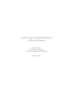
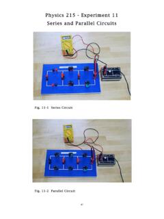
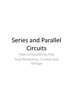
8 If the capacitor is then disconnected from the battery it will retain this charge and the potential across the capacitor will remain that of the battery. If a resistor is then connected across the capacitor, charge will flow through the resistor until the potential difference between the two terminals goes to zero. This series RC circuit is shown in Figure 6. The potential will decrease with time according to the relation: V(t) V0e t/ , where RC (1) V0 represents the voltage at time t = 0, and represents the time constant or time that it takes for the voltage to decrease by a factor of 1/e. Figure 6 Simple RC circuit The time dependence of the voltage is derived using Kirchhoff s law and the relations between current and voltage in the resistor and capacitor. Traversing the loop of Figure 6 clockwise, Kirchhoff s law tells us that: VR VC 0 (2) where VR and VC represent voltage drop across the resistor or capacitor, respectively.
9 It is important to note that if one applies a constant voltage to this circuit (which is what you will be asked to do) then the additional voltage source will be an additional term in the sum. This term is will be a constant. The result of the forthcoming differential equation is the same with the addition of a constant. These circuit elements are related to their voltages in the following ways: VR IRRQC CVC (3) (4) Experiment 1: RC Circuits 5 where QC is charge accumulation in the capacitor. Substituting these two equations into the Kirchhoff equation and solving for IR yields IR 1 RCQC (5) Since R and C are in series dQCdt IR 1 RCQC (6) Using the initial conditions Q=Q0 at t=0 the charge Q on the capacitor at some later time t is found by integration dQQ 1 RCdt0t Q0Q lnQQ0 1 RCtQ Q0e t/ (7) Since IR dQdt Q0 1 e t/ (8) we can determine the following: VR IRR Q0R 1 e t/ Q0Ce t/ V0e t/ (9) Equation (9) is the desired equation.
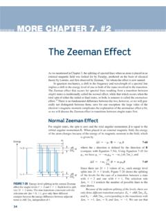
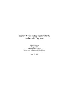
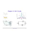
10 Recall that if the voltage is not zero but still constant, then the voltage equation above will be the same with the addition of a constant term. Experiment 1: RC Circuits 6 Question What is the propagated error of the time decay, , from the two point method (equation 10)? Figure 7 Exponential decay of a capacitor potential In the lab, you will be asked to determine from measurements of V(t), INDEPENDENT of any knowledge of R and are several ways to do this but the properties of the exponential function allow you to do it simply by measuring the voltage at only two times, t1, and t2. According to equation 1, the voltages at these times will be given by: V1 V0e t1/ and V2 V0e t2/ V1V2 e(t2 t1)/ t2 t1ln(V1/V2) (10) An especially simple pair of points can be chosen such that the second voltage is equal to the first voltage divided by e.