Transcription of Experiment 12: AC Circuits - RLC Circuit
1 Experiment 12: AC Circuits - RLC CircuitIntroductionAn inductor (L) is an important component of Circuits , on the same level as resistors (R) and capacitors(C). The inductor is based on the principle of inductance - that moving charges create a magnetic field (thereverse is also true - a moving magnetic field creates an electric field). Inductors can be used to producea desired magnetic field and store energy in its magnetic field, similar to capacitors being used to produceelectric fields and storing energy in their electric field. At its simplest level, an inductor consists of a coilof wire in a Circuit . The Circuit symbol for an inductor is shown in Figure far we observed that in an RC Circuit the charge, current, and potential difference grew and decayedexponentially described by a time constant.
2 If an inductor and a capacitor are connected in series in acircuit, the charge, current and potential difference do not grow/decay exponentially, but instead oscillatesinusoidally. In an ideal setting (no internal resistance) these oscillations will continue indefinitely with aperiod (T) and an angular frequency given by =1 LC(1)This is referred to as the Circuit s natural angular Circuit containing a resistor, a capacitor, and an inductor is called an RLC Circuit (or LCR), asshown in Figure 1b. With a resistor present, the total electromagnetic energy is no longer constant sinceenergy is lost via Joule heating in the resistor. The oscillations of charge, current and potential are nowcontinuously decreasing with amplitude. This is referred to asdampedoscillations.
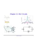
3 The oscillations in theRLC Circuit will not damp out if an external emf source supplies enough energy to account for the energylost from the resistor. This energy is supplied from an oscillating emf source with an alternating current(AC).If the applied voltage in an RLC is of the formE=E0sin( t+ )(2)whereE0is the maximum amplitude of the emf, then the potential difference across each component canbe written asVR=V0 Rsin( t)(3)VC=V0 Csin( t 2)(4)VL=V0 Lsin( t+ 2)(5)whereV0R,V0C, andV0 Lare the maximum (amplitude) voltages across the resistor, capacitor, and inductorcomponents respectively. The here is thedrivingangular frequency. Notice that the voltage across thecapacitorVClagsVRby 90 , and the voltage across the inductorVLleadsVRby 90 . All three voltagesare plotted in Figure (a)VVVVLCRALLRCCR(b)Figure 1: (a) Inductor Circuit symbol.
4 (b) An RLC 2: Phase relationships between voltages across the components of an RLC Circuit . UsingVRas areference,VLleads by 90 whileVClags by 90 . Note that the amplitude of the voltage for each componentmay not be equal as depicted but depend on the specific values of L, R and this lab we will only discussseriesRLC Circuits . Since the R, L, and C components are in series,the same current passes through them. The current in the Circuit can be expressed in the form of OhmsLaw asI=E0Z(6)where Z is theimpedenceof the Circuit defined asZ= R2+ ( L 1 C)2(7)The impedance of a Circuit is a generalized measurement of the resistance that includes the frequencydependent effects of the capacitor and the inductor. Notice from Equation 6 that the current I is at amaximum when Z is minimum.
5 Thus, for a given resistor R, the amplitude of the current is a maximumwhen L 1 C= 0; that is, when L=1 C(8)or written in terms of the angular frequency as =1 LC(9)The maximum value of the current occurs when thedrivingangular frequency matches thenaturalangularfrequency ( ) atresonance. In this lab we will study an RLC Circuit with an AC source to create aresonant and Analysis:1. You are given a resistor, an inductor and a capacitor with nominal values of R = 12 k , L = H,and C = 10 nF, respectively. Using the inductance meter / multimeter measure the values of R, Land C and compare them with the given Construct the Circuit shown in Figure 1b using the breadboard with jumper-wires. Make sure thatthe resistor is the last component closest to the ground end of the Turn on the signal generator and set the frequency of the oscillating signal to be approximately250 Hz (note: = 2 f).
6 The time varying voltages will be studied using the oscilloscope. Theoscilloscopes allow you to measure potential difference with respect to As a first exercise, we will observe the voltage on the oscilloscope when the two sources are inphase with each other. Connect the leads from CH1 and CH2 of the oscilloscope to the LRC circuitas shown in Figure 3. This means that both channels will measure the voltage across Make sure both signals are visible on the display. Adjust the Horizontal and Vertical scale knobs toobtain a suitable display on the Are the signals from CH1 and CH2 in phase with each other? Why is this the case? Sketch thesignals in your Change the display selector from y-t to x-y (x ).
7 Use the display button and the format buttonfound in the on-screen menu to toggle between the two settings. If both x and y are in phase witheach other (they both reach their peaks and valleys at the same instant), the oscilloscope shoulddisplay a straight line inclined at an angle (45 degrees if both inputs have the same magnitude andcalibration scale). Verify this. Just as you directly observed the waveform in Procedure 6, this isanother technique to check if the two signals are in phase with each other. This display is known asa Lissajous figure. Sketch this display in your report, remember to label the axis 1Ch 2 ROscilloscopeFigure 3: Oscilloscope connection for alternating current Circuit . Note that only the resistor part of theRLC Circuit is Change the settings to obtain the signal as in Procedure 5-6.
8 Disconnect CH2 from the Circuit andconnect it to Point A as shown in Figure 1b. In this position, CH1 is still measuring the voltageacross the resistor (VR), but CH2 is now measuring the voltage across all three components (VRLC).Adjust the vertical and horizontal scales to obtain the best Are the two signals in phase with each other? DoesVRLC lead or lagVR,and by how much? Sketchthis in your Observe the Lissajous figure for these two signals by repeating Procedure 7. Is this identical to theone you observed before? Sketch this in your report. You should now know what the Lissajous figureshould look like when the signals are in phase and out of phase with each Change the settings back to obtain the signal as in Procedure 8-9 (using the format button), butthis time, set the display to show only the signal from CH1, which isVR.
9 You should, however, leaveCH2 connected as Change the frequency of the signal generator (hint: you may want to increase the frequency) whilecontinuously observing the amplitude ofVR. Find the frequency where the amplitude ofVRis amaximum. Change the vertical scale and the vertical positioning as you wish to help you accuratelydetermine this frequency. Do not forget to read the frequency from the frequency counter. At thisfrequency, the current in the Circuit is also a maximum, sinceVR= IR. Thus, from Equations 6 and7, this is the resonant frequency of the RLC Now change the display setting so that you again see bothVRfrom CH1, andVRLC from CH2. FromEquations 8 and 9, thereactancefrom the inductor (XL= L) and the reactance from the capacitor4(XC= 1/ C) should cancel each other so that the impedence of the Circuit just depends on theresistor.
10 This means thatVRLC should be in phase withVR. Is this what you observe?14. Check this by observing the Lissajous figure at the resonant frequency. If the figure does not quiteshow the shape necessary for the two signals to be in phase, make the necessary adjustments to thefrequency until you are satisfied that they are now in phase with each other. Record this frequencyif it is different from the one you obtained Using Equation 9, calculate the theoretical value of the resonance frequency and compare it withthe value (or values if you have two different ones) you obtained experimentally. Take note that inEquation 9, you are calculating the resonanceangularfrequency .16. Calculate the phase constant for procedure 9 - that is,tan =XL XCR(10)Is the Circuit more inductive than capacitive or vice versa?