Transcription of Experiment 9: Centrifugal Pump - Islamic University of Gaza
1 Hydraulics Lab - ECIV 3122 Experiment (9): Centrifugal Pump Experiment 9: Centrifugal Pump Introduction: pumps fall into two main categories: positive displacement pumps and rotodynamic pumps . In a positive displacement pump, a fixed volume of fluid is forced from one chamber into another. One of the oldest and most familiar designs is the reciprocating engine, utilising a piston moving inside a cylinder. Steam pumps , the 'nodding donkey', stirrup pumps and hydraulic rams are all of this type. Animal hearts are also positive displacement pumps , which use volume reduction of one chamber to force flow into another chamber.
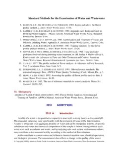
2 The FM50 pump is, by contrast, a rotodynamic machine. Rotodynamic (or simply dynamic) pumps impart momentum to a fluid, which then causes the fluid to move into the delivery chamber or outlet. Turbines and Centrifugal pumps all fall into this category. pumps Turbo-hydraulic (Kinetic) pumps Positive Displacement pumps Centrifugal Propeller Jet Screw Reciprocating Pump (Radial) (Axial) (Mixed) Description: The apparatus consists of a tank and pipework which delivers water to and from a small Centrifugal pump. The unit is fitted with electronic sensors which measure the process variables.
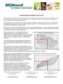
3 Signals from these sensors are sent to a computer via an interface device, and the unit is supplied with data logging software as standard. Pump speed and outlet pressure may be varied to allow the collection of performance data over a range of parameters. The inlet (suction) head pressure may be adjusted to investigate the onset of cavitation. An alternative impeller is also supplied so that the effect of impeller design may be studied. For more Details refer to Instruction Manual FM50. Figure 1: Centrifugal Pump Demonstration Unit Hydraulics Lab - ECIV 3122 Experiment (9): Centrifugal Pump Exercise B Objective To create head, power and efficiency characteristic curves for a Centrifugal pump.
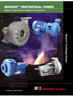
4 Theory One way of illustrating pump characteristics is to construct contour lines of constant power or efficiency on a graph of pump head plotted against pump discharge. These allow engineers to see the maximum efficiency of a pump over a range of operating parameters, which can assist in the selection of an appropriate pump to suit particular conditions. An example is given in Figure 2. Figure 2 Equipment Set Up If the equipment is not yet ready for use, proceed as follows: Ensure the drain valve is fully closed. If necessary, fill the reservoir to within 20cm of the top rim. Ensure the inlet valve and gate valve are both fully open.
5 Ensure the equipment is connected to the IFD7 and the IFD7 is connected to a suitable PC. The red and green indicator lights on the IFD7 should both be illuminated. Ensure the IFD7 is connected to an appropriate mains supply, and switch on the supply. Run the FM50-304 software. Check that 'IFD: OK' is displayed in the bottom right corner of the screen and that there are values displayed in all the sensor display boxes on the mimic diagram. Hydraulics Lab - ECIV 3122 Experiment (9): Centrifugal Pump Procedure Switch on the IFD7. Switch on the FM50 pump within the software using the Pump On button.
6 In the software, rename the current (blank) results table to '50%' (this will be the only table if results from Exercise A are not available). On the mimic diagram of the software, set the pump speed to 50%. The interface will increase the pump speed until it reaches the required setting. Allow water to circulate until all air has been f1ushed from the system. Partially closing and opening the inlet and gate valves a few times will help in priming the system and eliminating any bubbles caught within the valve mechanism. Leave the inlet valve fully open. Close the gate valve to give a flow rate Q of 0. (Note that the pump may not run well with the gate valve closed or nearly closed, as the back pressure produced is outside normal operating parameters.)
7 The pump should begin to run more smoothly as the Experiment progresses). Select the icon to record the sensor readings and pump settings on the results table of the software. Open the gate valve to allow a low flow rate. Allow sufficient time for the sensor readings to stabilise then select the icon to record the next set of data. Open the gate valve in small increments, allowing the sensor readings to stabilise then recording the sensor and pump data each time. Create a new results sheet by selecting the icon (you may also wish to save the results at this time to avoid losing the data in the event of problems).
8 Close the gate valve. Set the pump to 60%. Select the icon to record the sensor readings and pump settings on the new results table. Repeat as before, opening the gate valve in small increments and allowing the sensor readings to stabilise then recording the sensor and pump data each time. Close the gate valve. Repeat the procedure at 70%, 80%, 90% and 100%. Create a new results sheet for each setting (and save the results if desired- the same file may be overwritten each time as more data is added). For convenience, rename each sheet of results in the software with the pump setting. Ensure the results are saved after taking the final set of results.
9 Switch the pump off. If not proceeding directly to another exercise then switch off the IFD7 and close the FM50 software. Hydraulics Lab - ECIV 3122 Experiment (9): Centrifugal Pump Results On the same graph plot Total Head Ht against Flow Rate Q for each setting. Graphs may be produced using the software graph facility, in which case the resulting graph with multiple plots must be printed. Alternatively the results may be imported into a more sophisticated spreadsheet program that allows the following procedure to be performed. Select a value for efficiency, for example 40%.
10 On each line plotted, mark the points at which an efficiency of 40% is achieved (the data is unlikely to include recorded points at which the efficiency is exactly 40%, so estimate the points based on the values obtained). Where the pump performance at a particular setting does not ever correspond to the efficiency chosen, note whether the efficiency would lie above the line or to the right of the pump performance curve. Join the marked points to form a smooth curve. Repeat for other efficiency values. for example 35%.45% and 5090. to give a family of efficiency curves . Create and/or print a second head-flow rate graph for all pump frequencies.