Transcription of F Series Excess Flow Valves for LP-Gas and NH3 - Emerson
1 F SeriesD450008T012 Instruction ManualMCK-1060 May Series Excess Flow Valves for LP-Gas and NH3 !WarNiNGFailure to follow these instructions or to properly install and maintain this equipment could result in an explosion and/or fire causing property damage and personal injury or death. Fisher equipment must be installed, operated, and maintained in accordance with federal, state, and local codes and Fisher instructions. The installation in most states must also comply with NFPa No. 58 or aNSi standards. Only personnel trained in the proper procedures, codes, standards, and regulations of the LP-Gas or NH3 industries should install and service this equipment. !WarNiNGa break or leak down stream of an Excess flow valve that does not allow a flow equal to the valve flow rating will not actuate the Excess flow valve and could result in a fire or explosion from leaking gas.
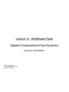
2 After the Excess flow valve closes, the leakage through the equalizing hole must be controlled or a hazard can be created. For this reason the operator must be familiar with the system shutoff Valves and close the system if an emergency occurs. reference NPGa-113 The Limitations of Excess Flow Check Valves for LP-Gas . introduction Scope of the Manual This instruction manual covers installation and maintenance for Fisher F Series Excess flow Valves used on LP-Gas and anhydrous ammonia. DOT Passive Shutdown Equipment requirement DOT regulations 49 CFR (n)(2) require certain cargo tanks transporting propane, anhydrous ammonia and other liquified compressed gases to be equipped with passive emergency discharge control equipment that will automatically shutoff the flow of product without human intervention within 20 seconds of an Figure 1.
3 F Series Excess Flow ValvesTYPE F110 TYPE F110aTYPE F100 TYPE F138 TYPE F130 TYPE F134 TYPE F190F Series2unintentional release caused by complete separation of a delivery hose. The design for each passive shutdown system must be certified by a Design Certifying Engineer (DCE) and all components of the discharge system that are integral to the design must be included in the DCE certification. The DCE certification must consider any specifications of the original component manufacturer. Specifications1. LP-Gas or NH3 service.* Nominal Pipe Operating Pressure: 250 psig (17,2 bar) Maximum Differential Pressure: 15 psig (1,0 bar) Closing Flow Tolerance: 10% to -20% of rated flow In the case of downstream ruptures in hose or piping, a variety of operating conditions routinely encountered during an unloading operation restrict the rate of flow through the Excess flow valve and make such a valve unsuitable to serve as the means of passive shutdown required under 49 CFR (n)(2).
4 Such variables include restrictions incorporated in the discharge system (due to pumps, pipe and hose length and dimensions, branching, elbows, aPPLiCaTiONiNLET CONNECTiON, NPS*OuTLETCONNECTiON, NPSTYPE raTED CLOSiNG FLOW, PrOPaNE(HOrizONTaL POSiTiON)DiFFErENTiaL PrESSurE,PSiG (bar)brassSteelLiquid GPM(l/min)Vapor SCFH (SCMH)25 Psig (1,7 bar) inlet100 Psig (6,9 bar) inletPortable Service (Torches, burners, etc.)Male POL9/16 18 UNF LHF110 (2,6)120 (3,4)204 (5,8) (0,51)F183 (5,7)335 (9,5)570 (16,1) (0,67)1/4 MNPTF173 (2,6)120 (3,4)204 (5,8) (0,51)F181 (5,7)335 (9,5)570 (16,1) (0,67)Soft NoseMale POL9/16 18 UNF LHF110A (2,6)120 (3,4)204 (5,8) (0,51)1/4 MNPTF173A In-Line1/4 MNPT1/4 FNPTF138 (6,8)377 (10,7)641 (18,2) (0,10)Male POL1/2 SAE FlareF202 (7,2)634 (18,0)1100 (31,2) (0,18)Tanks (Full or Half Coupling)3/4 MNPT3/4 FNPTF170 (25,0)1184 (33,5)2012 (57,0) (0,08)F100 (31,8)2010 (56,9)3417 (96,8) (0,17)F101 20 (75,7)3459 (98,0)5880 (167) (0,59)1-1/4 MNPT1-1/4 FNPT F102 33 (125)6300 (178)10 630 (301) (0,74)F105 55 (208)9982 (283)16 967 (481) (0,74)2 MNPT2 FNPTF106 85 (322)18 513 (524)31 467 (891) (0,18)F107 100 (379)20 796 (589)35 349 (1001) (0,25)In-Line1 FNPT1 FNPTF130 25 (94,6)5287 (150)8986 (254))
5 (0,23)1-1/2 FNPT1-1/2 FNPTF131 60 (227)11 694 (331)19 877 (563) (0,32)2 FNPT2 FNPTF132 95 (360)19 874 (563)33 877 (959) (0,14)F133 155 (587)29 202 (827)49 718 (1408) (0,29)Tanks (Full or Half Coupling)1-1/2 MNPT x 1 FNPT1 FNPTF134 28 (106)5181 (147)8806 (249) (0,19)2-1/2 MNPT x 1-1/2 FNPT1-1/2 FNPTF135 60 (227)12 000 (340)20 290 (575) (0,36)Tanks(1) (Full or Half Coupling)2 MNPT2 MNPT x 1-1/4 FNPT F19080 (303)15 400 (436)26 250 (743) (0,26) F191105 (397)18 800 (532)32 000 (906) (0,61)3 MNPT2 MNPT F194165 (625)32 800 (929)55 950 (1585) (0,21) F195260 (984)50 650 (1434)86 350 (2445) (0,48)3 MNPT3 MNPT X 2 FNPT F198165 (625)33 000 (935)56 250 (1593) (0,21) F199260 (984)49 500 (1402)84 350 (2389) (0,49)F Series3 Valves with brass materials must not be used on anhydrous ammonia service. installation CauTiONDo not install the valve in any piping which tends to restrict the valve inlet.
6 This may prevent the Excess flow valve from closing. Flow through the Excess flow valve must be in the same direction as the flow arrow stamped on the valve. 1. A rule of thumb for sizing Excess flow Valves is to choose a valve with a closing flow times the maximum operating flow. For surge conditions, 2 times maximum flow may be required. However, the Excess flow valve s closing flow rate must be less than the capacity of the LP-Gas or NH3 system in which the valve is being used. The flow rating of the piping, fittings, pump, Valves , and hose on both the inlet and outlet of the Excess flow valve must be greater than the flow rating of the Excess flow valve. If branching, piping length, additional Valves , reduction in pipe size, elbows, or other necessary components in the piping system create restrictions which reduce the flow rating to less than that of the Excess flow valve rating, the valve will not give Excess flow protection, and additional Excess flow Valves must be installed at these points.
7 2. Brass Valves are not suitable for NH3 applications. 3. Manually operate the Excess flow valve s poppet before installation to assure parts were not damaged in shipment or blocked with dirt or foreign material. 4. Use pipe dope on the male threads of the valve or the pipeline. PTFE tape or PTFE pipe dope compound is recommended for the male threads of the larger Valves such as the NPS 2 and 3 (DN 50 and 80) sizes. 5. After the Excess flow valve is installed, the system should be tested for Excess flow valve operation by simulating a break downstream in the system at the furthermost point being protected. To test the unit, pressure the system and then open a shutoff vave quickly at the farthest point in the piping that the Excess flow valve is intended to protect.
8 There should be a sudden decrease in flow, indicating that the valve has closed and is working properly. reductions in pipe diameter, or a number of other in-line Valves or fittings), low operating pressure as a result of ambient temperature, or a partially closed valve downstream from the Excess flow valve. Due to the variety of conditions, in the case of a hose separation, that can restrict the rate of flow below the level necessary to activate the Excess flow Valves , the F Series Excess flow Valves cannot be used to satisfy the passive shutdown equipment requirement under/in 49 CFR (n)(2). Also, a Design Certifying Engineer cannot include the F Series Excess flow valve as a component of the discharge system in any DCE certification under 49 CFR (n)(2). !ExPLOSiON HazarDDO NOT uSE the F Series Excess flow Valves to satisfy the passive shutdown equipment requirement in 49 CFr (n)(2).
9 DO NOT include the F Series Excess flow Valves in a DCE certification under 49 CFr (n)(2). The cargo tank manufacturer must install some other equipment that satisfies the requirement for passive shutdown capability under 49 CFr (n)(2). Failure to follow this warning could result in serious personal injury or property damage from a fire or explosion in the event of an unintentional release of product during an unloading operation. Description Excess flow check Valves close when the flow rate of vapor or liquid exceeds the valve s rated flow capacity. They are used to protect cylinder, tank, and piping systems. The Valves are available in a variety of sizes and body configurations. When flow exceeds the valve s setting, the valve closes and remains closed until the system equalizes. A built-in equalizing passage automatically opens the valve once pressures on both sides of the poppet are CauTiONif the valve is to be used in service other than LP-Gas or anhydrous ammonia, contact the factory to determine if the valve materials are suitable for the particular service.
10 F SeriesThe Emerson logo is a trademark and service mark of Emerson Electric Co. All other marks are the property of their prospective owners. Fisher is a mark owned by Fisher Controls, Inc., a business of Emerson Process contents of this publication are presented for informational purposes only, and while every effort has been made to ensure their accuracy, they are not to be construed as warranties or guarantees, express or implied, regarding the products or services described herein or their use or applicability. We reserve the right to modify or improve the designs or specifications of such products at any time without Process Management does not assume responsibility for the selection, use or maintenance of any product. Responsibility for proper selection, use and maintenance of any Emerson Process Management product remains solely with the purchaser.