Transcription of Failure Modes and Fusing of TVS Devices - Vishay
1 Vishay GENERAL SEMICONDUCTORSD iodes and RectifiersApplication NoteFailure Modes and Fusing of TVS NOTE Revision: 15-Nov-161 Document Number: 88440 For technical questions within your region: DOCUMENT IS SUBJECT TO CHANGE WITHOUT NOTICE. THE PRODUCTS DESCRIBED HEREIN AND THIS DOCUMENTARE SUBJECT TO SPECIFIC DISCLAIMERS, SET FORTH AT voltage suppressors (TVS) will fail if they are subjected to conditions beyond their designed limits. It is, therefore, important to understand the types of Failure Modes of TVS Devices before designing them into a circuit application. There are three basic types of Failure Modes : shorts, open, and degraded (outside of the specification limits). Although the silicon avalanche junction transient voltage suppressor (SAJTVS) will first fail short in most applications, there is always one transient event that will cause it to open initially.
2 In this case, the transient energy is large and of short duration that the silicon chip itself a TVS device does short, follow-on operating current may cause the device to open. Fusing of the line is recommended in all applications. Shorted Devices will start to conduct current away from the circuit or system affecting its performance. Open Devices are transparent to the circuit / system and will not usually distribute circuit functions. In either case, it is difficult to determine if the TVS device is still functioning while in the circuit. Degraded TVS Devices are most difficult to detect in the circuit. These can be Devices with high leakage currents which may not adversely affect circuit performance, except under elevated operating temperatures. All three types of Failure Modes are discussed in this applications note along with the design practices for Fusing the line when a device does the thought that a TVS device can fail, there are some additional terms that designers would like to impose on the protector to ease this problem.
3 One such term is a Fail Safe condition. The term Fail Safe implies some level of safety which cannot be used in connection with the TVS device. Due to the very nature of the unknown transient threat, there are no 100 % guarantees. Fail Safe is one of the most misunderstood terms regarding transient protection. It is important to define the term and discuss why it should not be used in reference to a TVS have different meanings to different people which is the case with the term Fail Safe. A TVS device cannot assure a fail safe environment. By nature, a TVS device will fail when subjected to a transient beyond its designed capability. If the circuit or system is not properly fused, a shorted TVS device can become a safety hazard conducting operating currents through the return path. Even with the proper design-in and adherence to good engineering practices, this term should not be used in describing the function of the protection network.
4 Quite often, the unknown transient threat along with some of the guess work regarding the sizing (peak pulse power rating) of the TVS device will suggest some level of risk in the overall protection system. The risk, in this case, is the trial and error method used to guarantee proper TVS device selection versus its location. This type of selection process may take some time to accomplish when the transient threat cannot be fully defined. Fail Safe may be used in conjunction with a complete systems approach, but not with a component such as a TVS MODESTVS Devices will fail in one of three Modes . These are shorts, opens, and degraded Devices . In most applications, the preferred method of Failure is a short. A short is defined when the TVS device has a resistance value of less than 1 at a DC voltage of V (ref. ANSI/IEEE ). In the more practical world, a shorted device will start to conduct a significant amount of operating current to ground, Fig.
5 1 - Current Path for Shorted Surge ProtectorThe actual current shunted to ground will depend upon the resistance in the line ahead of the TVS device. For the power line, this could mean a significant amount of current depending upon the available current from the power supply or source. With data lines, this can be somewhat limited but will depend upon the operating current of the circuit. Data lines operating in the milliampere range are more difficult to fuse. In either case, it is important to provide some type of Fusing in the line to open up the circuit when a TVS device does short, Fig. PowerBus Line+ProtectedEquipmentorComponentFailur e Modes and Fusing of TVS DevicesApplication General SemiconductorsAPPLICATION NOTE Revision: 15-Nov-162 Document Number: 88440 For technical questions within your region: DOCUMENT IS SUBJECT TO CHANGE WITHOUT NOTICE. THE PRODUCTS DESCRIBED HEREIN AND THIS DOCUMENTARE SUBJECT TO SPECIFIC DISCLAIMERS, SET FORTH AT 2 - Fuse Location Relative to TVS DeviceThe Fusing element must take into consideration two possibilities.
6 First is the ability to handle the required transient current without interrupting the circuit functions. Second, it has to be able to open the line when the TVS device does open TVS device is defined as a diode that has a breakdown voltage VBR greater than 150 % of the pretested value at an applied test current (lP) (Ref. ANSI/IEEE ). For this test, the unit must be taken out of the circuit for verification. An open device in the circuit will not exhibit any of the standard electrical characteristics such as leakage current or clamping voltage. Once out of the circuit, the TVS device can be tested on a curve tracer for verification of the open an improperly fused circuit, a device that has been shorted can become open after an applied operating current is allowed to conduct through the device for a period of time. Fig. 3 shows the Fusing currents and time durations for each of the major axial lead type packages.
7 When this occurs, there is usually some visible evidence in the form of a burn mark on or within the device indicating an open that degrade are more difficult to detect. These types of failed Devices will exhibit an increase in the reverse leakage current under normal operating voltages (equivalent to the stand-off voltage). According to ANSI/IEEE , a degraded Failure mode has occurred when the avalanche junction surge suppressor has a stand-by current greater than the maximum specified. On the power bus line, this level of current reaches the upper limit of the power supply current or when the unit shorts from the increased current conduction. For data lines, this value may be much less due to the fact that there can be loss of data transmission of information. A device will act as a low impedance shunt path to 3 - Clearing Time for Transient Voltage Suppressor Device - Fail Opened ConditionAs discussed earlier, Fail Safe is discouraged in the description of a Failure mode for TVS Devices .
8 For some, the term can be a desirable characteristic in that the unit will protect up to a specific level. To others it can mean that the device should provide protection because of the fail short or open condition. While both may be true, the TVS device should not be described as a fail safe product due to the fact that no one can guarantee a specific type of device Failure mode. The transient threat and the location of the transient voltage suppressor in the equipment will also have a major influence on the type of Failure mode. In some applications, the transient currents and impulse waveform cannot be completely defined. As a result, the correct TVS device may not be designed in. In this case, the TVS device application is a trial and error method as suggested earlier. A TVS device is designed to withstand a specific level (power) of transient threat as defined by a peak pulse power rating versus pulse width curve, Fig.
9 Manufacturers will provide a peak pulse power versus time curve on their individual product datasheets. This will provide the designer with the maximum power limit within a product family or series of Devices . It is up to the circuit or system designer to translate this product information into the appropriate threat level. Threat levels should always be defined in terms of the peak current amplitude and impulse waveform rather than calculate the energy of the TVS device from the power curve. Energy is not a key parameter here due to the fact that the energy contained within the transient event is not the energy deposited in the TVS device. Equating the transient current threat to the peak pulse current rating of the TVS will ensure proper device selection and the continuous operation of the protector in the application. There will, however, be those applications in which the actual transient current cannot be defined.
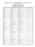
10 At best, the identification of the source of the threat is necessary; that is, lightning, switching, ESD or NEMP. From this information, the manufacturer can provide the direction for initial product selection.+DC PowerBus LineFusePower InputPCB1000100101100101000t - Clearing Time (s)I - Current (A)SA Modes and Fusing of TVS DevicesApplication General SemiconductorsAPPLICATION NOTE Revision: 15-Nov-163 Document Number: 88440 For technical questions within your region: DOCUMENT IS SUBJECT TO CHANGE WITHOUT NOTICE. THE PRODUCTS DESCRIBED HEREIN AND THIS DOCUMENTARE SUBJECT TO SPECIFIC DISCLAIMERS, SET FORTH AT 4 - Peak Pulse Power vs. Pulse TimeProduct selection begins by equating the circuit operating voltage to the stand-off voltage of the TVS device, Table 1. Next, as discussed above, it is necessary to equate the transient current to the peak pulse current of the TVS device.