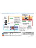
Transcription of Fan Application - Greenheck Fan
1 Fan Application . FA/127-11. A technical bulletin for engineers, contractors and students in the air movement and control industry. Measuring Belt Tension This article discusses several methods for measuring inspected for any cracks or fraying as these indicate the belt tension for V-belts commonly used in HVAC belt wear. applications . Tensioning the belt is often done Measuring Belt Tension by Deflection during initial startup and periodically throughout its life for preventative maintenance. Common belt Measuring belt tension by deflection evaluates the tensioning methods are to measure belt tension by force needed to achieve a given belt deflection. deflection, to measure belt tension by frequency, The recommended force can be referenced in the and to use a Tension Finder.
2 While there are other table at the end of the article. This article addresses manufacturers of belt tensioning equipment, the using a single stem tensiometer. A tensiometer is a following discussion and steps are based on Carlisle tool that measures the force required to move the products. tensiometer plunger a given distance. This force can be compared to a table of recommended tension Proper Belt Tension forces to determine the status of the belt. The proper tension for operating a V-belt drive is the lowest tension at which the belts will not slip at peak load conditions. For applications without a variable frequency drive (VFD) or starter, and the motor is ran across the line , the tension must be able to handle the increased motor torque during startup.
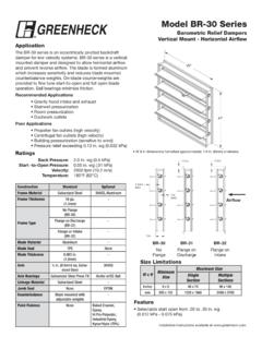
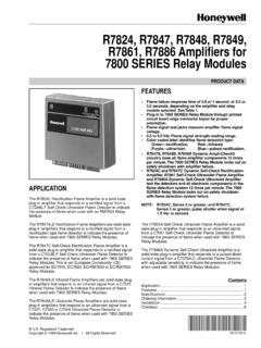
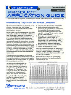
3 For slow start VFD applications , the belt tension must handle the actual brake horsepower of the fan at the fan shaft. For V-belts, after initial installation tensioning, a re-tensioning of the belt is recommended after a period of operation, usually one to two days. Belt tension should be checked periodically, about every three to six months. A more frequent inspection for noise or vibration is recommended. Figure 1. Belt Span Length Under-tensioned belts can slip, generating heat that often results in cracking and eventual belt Required equipment: tensiometer, tape measure, failure. Over-tensioned belts will create excessive straight edge (for single belt drives). stretching in the belt and reduce both belt and bearing life as the bearing loads will increase.
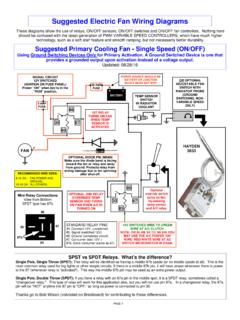
4 While 1. Turn off power to the motor and follow lock out, checking the belt tension, the belts should also be tag out procedures. Box 410 Schofield, WI 54476 Fax Copyright 2011 Greenheck Fan Corp. Greenheck Product Application Guide 2. Measure the span length of the belt. See Measuring Belt Tension by Figure 1. Span length is the distance the Frequency belt spans between the sheaves. The desired belt deflection is 1/64 of an inch By measuring the natural frequency of for every inch of belt span. For example, the tensioned belt, the tension of the if the span length is 32 inches, the desired belt can be calculated. This method is belt deflection is inch. applicable for V and banded belts. 3. Set the large O ring on the tensiometer One way to measure the natural to the desired deflection determined in frequency of a belt is to use Carlisle's Step 2.
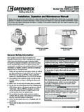
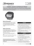
5 See Frequency-Finder . The Frequency- Figure 2. Finder uses a laser sensor to measure the frequency of a vibrating belt. This 4. Set the small frequency can then be compared to the O ring on the recommended frequency calculated tensiometer to with the software that accompanies the the zero mark. instrument. See Figure 2. Figure 2. Carlisle Tensionmeter Required equipment: Frequency- 5. Holding the (Carlisle Part No. Finder, Carlisle's Drive Engineer tensiometer 102761) software. as indicated in Figure 2, press the opposing end of the 1. Turn off power to the motor and follow lock out, tensiometer to the midpoint of the belt span tag out procedures. as indicated in Figure 1. Press down on the 2. Use Carlisle's Drive Engineer software to tensiometer (deflecting the belt) until the large calculate the desired minimum and maximum O ring is even with the original location of frequency for a given belt.
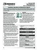
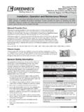
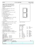
6 The frequency the belt. For a single belt drive, the tensiometer directly correlates with the belt tension. A higher should be depressed until the large O ring frequency relates to a higher belt tension. is lined up with the bottom of the straight edge placed on the outside rims of the two 3. Turn on the sheaves. For a multiple belt drive, depress the Frequency-Finder. tensiometer until the large O ring is even with The laser light the top of the next belt. Take a reading from each will turn on. The belt for an average. Frequency-Finder is pictured in 6. The small O ring now indicates the force (lbs) Figure 3. required to get the desired belt deflection. Check this reading against the recommended minimum 4.
7 Tap or pluck the belt deflection force in the Recommended free belt span to Minimum Belt Deflection Force table at the end induce vibration of this document. in the belt. Figure 3; Carlisle Frequency- Finder . 7. Tighten or loosen the belt accordingly to achieve 5. Hold the laser (Carlisle Part No. 109061). the recommended minimum belt deflection probe within one force. Tightening the belt will increase the inch above the free force; loosening the belt will decrease the belt belt span with the laser facing the outside of the deflection force. belt. 2 Fan Application FA/127-11. Greenheck Product Application Guide 6. A successful measurement will be conveyed by 4. Scribe a line on the belt perpendicular to the an audible beep followed by the frequency being direction of travel.
8 The Tension-Finder can be displayed (in Hz) on the LCD display of the used as a square. Frequency-Finder. 5. Place the start slot of the Tension-Finder over the 7. Compare the reading from Step 6 to the desired line scribed in Step 4. range determined in Step 2. If the reading is 6. Attach the spring to the belt with the scribed line below the desired frequency range, tighten the still in the start slot of the Tension-Finder. For belt. If the reading is above the desired range, reference, if the spring slips scribe a line on the loosen the belt. belt at the spring end of the Tension-Finder. Using Tension-Finder . 7. Using the Recommended Tensioning Slots table, A Tension-Finder can be used to set the tension determine the required tensioned slot for belt for Carlisle belt lines listed in the Recommended line and belt use.
9 Tensioning Slots table. A Tension-Finder should not be used with aramid or glass cord belts as it could 8. Tension the belt until the scribe line from Step 4 is result in damage to the equipment. The Tension- displayed in the designated slot of the Tension- Finder is a gauge used to set the correct tension in Finder as determined in Step 7. See Figure 4. the belt by measuring the amount of stretch in the belt while in tension. Required equipment: Tension-Finder, pen or marker. 1. Turn off the power to the motor and follow lock out, tag out procedures. 2. Install the belts loosely on the aligned sheaves. 3. Increase the center distance of the sheaves to apply enough tension to the belts to remove the slack.
10 Figure 4; Carlisle Tension-Finder on a V-belt. Recommended Tensioning Slots (Carlisle Part No. 108039-A). Slot No. Belt Lines 9. Remove the Tension-Finder from the belt before New Belt Used Belt operation. AP, BP, CP, DP, RBP, RCP, RDP. A, B, C 2 1. AX, BX, CX, DX, RBX, RCX, RDX. 5V, 8V. d m m ende R3V, R5V, R8V Reco um Belt n 5VX, 8VX Minim n Force o ctio 3 2 Defle ack page R3VX, R5VX, R8VX b R5VL. SPZX, SPAX, SPBX, SPCX. Fan Application FA/127-11 3. Greenheck Product Application Guide Recommended Minimum Belt Deflection Force Belt Section Small Sheave Drive Ratio Speed Range Diameter & Over 3V 1200-3600 1200-3600 1200-3600 1200-3600 1200-3600 5V 900-1800 900-1800 900-1800 700-1200 8V 900-1800 900-1800 700-1500 700-1200 400-1000 3VX 1200-3600 1200-3600 1200-3600 1200-3600 1200-3600 1200-3600 5VX 1200-3600 1200-3600 1200-3600 1200-3600 900-1800 900-1800 8VX 900-1800 900-1800 700-1500 700-1200 400-1000 AP 1800-3600 A 1800-3600 1800-3600 1800-3600 BP 1200-1800 B 1200-1800 1200-1800 1200-1800 CP 900-1800 C 900-1800 900-1800 700-1500 DP 900-1500 D 900-1500 700-1200 700-1200 AX 1800-3600 1800-3600 1800-3600 1800-3600 BX 1200-1800 1200-1800 1200-1800