Transcription of Features
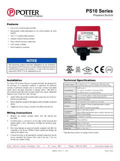
1 PS40 SeriesSupervisory Pressure Switch5400930 - REV H 2/20 PAGE 1 OF 4 Potter Electric Signal Company, LLC St. Louis, MO Phone: 866-956-0988 / Canada 888-882-1833 document contains important information on the installation and operation of PS40 pressure switches. Please read all instructions carefully before beginning installation. A copy of this document is required by NFPA 72 to be maintained on Potter PS40 Series Supervisory Pressure Actuated Switches are designed primarily to detect an increase and/or decrease from normal system pressure in automatic fire sprinkler systems.
2 Typical applications are: air/nitrogen supervision in dry pipe and pre-action systems, pressure tanks, air supplies, and water supplies. The PS40-1 has one switch and is factory set to activate at approximately 30 psi (2,1 bar) on a decrease in pressure. The PS40-2 has two switches. The Low switch is factory set to activate at approximately 30 psi (2,1 bar) on a decrease in pressure. The High switch is factory set to activate at approximately 50 psi (3,5 bar) on an increase in pressure. NFPA 72 requires a supervisory signal if the pressure increases or decreases by 10 psi from normal.
3 The PS40 is factory set for a normal air pressure of 40 psi. See section heading Adjustments and Testing if other than factory set point is Connect the PS40 to the system side of any shutoff or check Apply Teflon tape to the threaded male connection on the device. (Do not use pipe dope)3. Device should be mounted in the upright position. (Threaded connection down)4. Tighten the device using a wrench on the flats on the device. Technical SpecificationsConduit EntrancesTwo knockouts for 1/2 conduit provided.
4 Individual switch compartments and ground screw suitable for dissimilar voltagesContact RatingsSPDT (Form C) Amps at 125/250 VAC, Amps at 30 VDCOne SPDT in PS40-1, Two SPDT in PS40-2 Cover TamperCover incorporates tamper resistant fastener that requires a special key for removal. One key is supplied with each device. Differential Typical 1 lb. at 10 psi (,07 at ,7 bar) 4 lbs at 60 psi (,28 at 4,1 bar) (9,6cm) (8,1cm) (10,7cm)HEnclosureCover: Weather/UV/Flame Resistant High Impact CompositeBase: Die Cast All parts have corrosion resistant finishesEnvironmental Limitations-40 F to 140 F (-40 C to 60 C)NEMA 4/IP66 Rated Enclosure indoor or outdoor when used with NEMA 4 conduit fittingsFactory AdjustmentPS40-1 operates on decrease at 30 psi (2,1 bar)PS40-2 operates on increase at 50 psi (3,5 bar) and on decrease at 30 psi (2,1 bar)Maximum System Pressure300 psi (20,68 bar)Pressure ConnectionNylon 1/2 NPT malePressure Range10-60 psi (,7-4,1 bar)
5 Service UseNFPA 13, 13D, 13R, 72*Specifications subject to change without One or two switch models available Independent switch adjustment on two switch models, no tools needed Two 1/2 conduit/cable entrances Separate isolated wiring chambers Non-corrosive pressure connection Non-Conductive Enclosure Vds version availableDRAFT 15400930 - REV H 2/20 PAGE 2 OF 4 Potter Electric Signal Company, LLC St. Louis, MO Phone: 866-956-0988 / Canada 888-882-1833 SeriesSupervisory Pressure SwitchWiring Instructions1.
6 Remove the tamper resistant screw with the special key If it is necessary to remove the sealed knockouts, carefully place a screwdriver on the edge of the knockout and sharply apply a force sufficient to dislodge the knockout plug. See Fig. Run wires through an approved conduit connector and affix the connector to the device. A NEMA-4 rated conduit fitting is required for outdoor Connect the wires to the appropriate terminal connections for the service intended. See Figures 2,4,5 and 6.
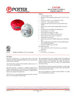
7 See Fig. 7 for two switch one conduit 1 NOTE: To prevent leakage, apply Teflon tape sealant to male threads [ ] [ ] [ ] [ ] [ ] [ ]GROUNDSCREWSDWG# 930-11/2" NPTADJUSTMENTKNOBO utgoingIncomingSwitch Clamping Plate TerminalFig 2 Typical Sprinkler ApplicationsFig 3 GONGMOTORWATERTESTBY-PASSWATERVALVEOS & YVALVEALARMPRESSURESWITCHPS10 CHECKVALVEVALVECHECKBVLVALVETESTBLEEDERA IR LINESHUT-OFFVALVEPS40 SUPERVISORY PRESSURE SWITCHDWG. #924-1 ARBVSDRY PIPEVALVEA djustment and TestingNOTE: Testing the PS40 may activate other system connected devices.
8 The operation of the pressure supervisory switch should be tested upon completion of installation and periodically thereafter in accordance with the applicable local, national and NFPA codes and standards and/or the authority having jurisdiction (manufacturer recommends quarterly or more frequently). The use of a Potter BVL (see product bulletin 5400799 for details) is recommended to facilitate setting and testing of the PS40 pressure switch . When a BVL (bleeder valve) is used, the pressure to the switch can be isolated and bled from the exhaust port on the BVL without affecting the supervisory pressure of the entire system.
9 See Fig. operation point of the PS40 Pressure switch can be adjusted to any point between 10 and 60 psi (0,7 - 4,11 bar) by turning the adjustment knob(s) clockwise to raise the actuation point and counter clockwise to lower the actuation point. In the case of the PS40-2, both switches operate independent of each other. Each switch may be independently adjusted to actuate at any point across the switch adjustment range. If the pressure needs to be adjusted from the factory settings, adjust the system pressure to the desired trip point.
10 Use an ohmmeter on the appropriate contact (COM and 2 for pressure decrease and COM and 1 for pressure increase). Adjust the knurled knob until the meter changes state. At that point the switch is set for that particular pressure. Final adjustments should be verified with a pressure position of the top of the adjustment knob across to the printed scale on the switch bracket can be used to provide an approximate visual reference of the pressure switch uninsulated section of a single conductor should not be looped around the terminal and serve as two separate connections.