Transcription of FEATURES - TDK
1 INMP441 Omnidirectional Microphone with Bottom Port and I2S Digital Output GENERAL DESCRIPTION The INMP441 is a high -performance, low power, digital-output, omnidirectional MEMS microphone with a bottom port. The complete INMP441 solution consists of a MEMS sensor, signal conditioning, an analog-to-digital converter, anti-aliasing filters, power management, and an industry-standard 24-bit I S interface. The I S interface allows the INMP441 to connect directly to digital processors, such as DSPs and microcontrollers, without the need for an audio codec in the system. The INMP441 has a high SNR, making it an excellent choice for near field applications. The INMP441 has a flat wideband frequency response, resulting in natural sound with high intelligibility. The INMP441 is available in a thin 1 mm surface-mount package. It is reflow- solder compatible with no sensitivity degradation. The INMP441 is halide free.
2 *Protected by Patents 7,449,356; 7,825,484; 7,885,423; and 7,961,897. Other patents are pending. APPLICATIONS Teleconferencing Systems Remote Controls Gaming Consoles Mobile Devices Laptops Tablets Security Systems FEATURES Digital I S Interface with high -Precision 24-Bit Data high SNR of 61 dBA high Sensitivity of -26 dBFS Flat Frequency Response from 60 Hz to 15 kHz Low Current Consumption of mA high PSR of -75 dBFS Small 1 mm Surface-Mount Package Compatible with Sn/Pb and Pb-Free Solder Processes RoHS/WEEE Compliant FUNCTIONAL BLOCK DIAGRAM ORDERING INFORMATION PART TEMP RANGE INMP441 ACEZ-R0* 40 C to +85 C INMP441 ACEZ-R7 40 C to +85 C EV_INMP441 EV_INMP441-FX * 13 Tape and Reel 7 Tape and reel to be discontinued. Contact for availability. INMP441 ADCPOWERMANAGEMENTSCKSDWSGNDGNDGNDVDDFIL TERI2 SSERIALPORTHARDWARECONTROLL/RCHIPEN BOTTOM TOP InvenSense reserves the right to change the detail specifications as may be required to permit improvements in the design of its products.
3 InvenSense Inc. 1745 Technology Drive, San Jose, CA 95110 +1(408) 988 7339 Document Number: DS-INMP441-00 Revision: Rev Date: 05/21/2014 INMP441 TABLE OF CONTENTS General Description .. 1 Applications .. 1 FEATURES .. 1 Functional Block Diagram .. 1 Ordering Information .. 1 Table of Contents .. 2 Specifications .. 4 Table 1. Electrical Characteristics .. 4 Table 2. I2S Digital Input/Output Characteristics .. 5 Table 3. Serial Data Port Specifications .. 5 Timing Diagram .. 5 Absolute Maximum Ratings .. 6 Table 4. Absolute Maximum Ratings .. 6 ESD Caution .. 6 Soldering 7 Table 5. Recommended Soldering Profile* .. 7 Pin Configurations And Function Descriptions .. 8 Table 6. Pin Function Descriptions .. 8 Typical Performance Characteristics .. 9 Theory of Operation .. 10 Understanding Sensitivity .. 10 Power Management .. 10 Normal Operation .. 10 Standby Mode .. 10 Power-Down Mode .. 10 Startup.
4 10 I S Data Interface .. 11 Data Output Mode .. 11 Data Word Length .. 11 Data-Word Format .. 11 Digital Microphone Sensitivity .. 12 Synchronizing Microphones .. 13 Digital Filter Characteristics .. 13 high -Pass Filter .. 13 Table 7. high Pass Filter Characteristics .. 13 Low-Pass Filter .. 13 Applications Information .. 15 Page 2 of 21 Document Number: DS-INMP441-00 Revision: INMP441 Power-Supply Decoupling .. 15 Supporting Documents .. 16 Evaluation Board User Guide .. 16 Application Notes (Product Specific) .. 16 Application Notes (General) .. 16 PCB Design And Land Pattern Layout .. 17 PCB Material And Thickness .. 18 Handling Instructions .. 18 Pick And Place Equipment .. 18 Reflow Solder .. 18 Board 18 Outline Dimensions .. 19 Ordering Guide .. 20 Revision History .. 20 Compliance Declaration Disclaimer .. 21 Page 3 of 21 Document Number: DS-INMP441-00 Revision: INMP441 SPECIFICATIONS TABLE 1.
5 ELECTRICAL CHARACTERISTICS (TA = 40 to 85 C, VDD = to V, CLK = MHz, CLOAD = 30 pF, unless otherwise noted. All minimum and maximum specifications are guaranteed across temperature, voltage, and clock frequency specified in Table 1, Table 2, Table 3, unless otherwise noted. Typical specifications are not guaranteed.) PARAMETER CONDITIONS MIN TYP MAX UNITS NOTES PERFORMANCE Directionality Omni Sensitivity 1 kHz, 94 dB SPL 29 26 23 dBFS 1 Signal-to-Noise Ratio (SNR) 20 Hz to 20 kHz, A-weighted 61 dBA Equivalent Input Noise (EIN) 20 Hz to 20 kHz, A-weighted 33 dBA SPL Dynamic Range Derived from EIN and maximum acoustic input 87 dB Frequency Response Low frequency 3 dB point 60 Hz 2 high frequency 3 dB point 15 kHz Total Harmonic Distortion (THD) 105 dB SPL 3 % Power-Supply Rejection (PSR) 217 Hz, 100 mVp-p square wave superimposed on VDD = V 75 dBFS Maximum Acoustic Input Peak 120 dB SPL Noise Floor 20 Hz to 20 kHz, A-weighted, RMS 87 dBFS POWER SUPPLY Supply Voltage (VDD) V Supply Current (IS)
6 VDD = V Normal Mode mA Standby mA Power Down 2 A VDD = V Normal Mode mA Standby mA Power Down A DIGITAL FILTER Group Delay sec fS = 48 kHz 359 s fS = 16 kHz 1078 s Pass-Band Ripple dB Stop-Band Attenuation 60 dB Pass Band fS kHz Note 1: The peak-to-peak amplitude relative to peak-to-peak amplitude of (224 1.) The stimulus is a 104 dB SPL sinusoid having RMS amplitude of Pa. Sensitivity is relative to 1 Pa. Note 2: See Figure 4 and Figure 5. Page 4 of 21 Document Number: DS-INMP441-00 Revision: INMP441 TABLE 2. I2S DIGITAL INPUT/OUTPUT CHARACTERISTICS PARAMETER CONDITIONS MIN TYP MAX UNITS NOTES DIGITAL INPUT Input Voltage high (VIH) L/R, WS, SCK x VDD VDD V 1 Input Voltage Low (VIL) L/R, WS, SCK 0 x VDD V 1 SD DIGITAL INPUT Voltage Output Low (VOL) VDD = V, ISINK = mA VDD V 1 Voltage Output Low (VOL) VDD = V, ISINK = mA VDD V 1 Voltage Output high (VOH) VDD = V, ISINK = mA VDD V 1 Voltage Output high (VOH) VDD = V, ISINK = mA VDD V 1 Voltage Output Low (VOL) VDD = V, ISINK = mA VDD V 1 Voltage Output Low (VOL) VDD = V, ISINK = mA VDD V 1 Voltage Output high (VOH) VDD = V, ISINK = mA VDD V 1 Voltage Output high (VOH) VDD = V, ISINK = mA VDD V 1 Note 1: Limits based on characterization results; not production tested.
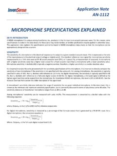
7 TABLE 3. SERIAL DATA PORT TIMING SPECIFICATIONS PARAMETER CONDITIONS MIN TYP MAX UNITS NOTES tSCH SCK high 50 ns tSCL SCK low 50 ns tSCP SCK period 312 ns fSCK SCK frequency MHz tWSS WS setup 0 ns tWSH WS hold 20 ns fWS WS frequency 50 kHz TIMING DIAGRAM Figure 1. Serial Data Port Timing SCKWSSDtSCPtSCHtSCLtWSHtWSSPage 5 of 21 Document Number: DS-INMP441-00 Revision: INMP441 ABSOLUTE MAXIMUM RATINGS Stress above those listed as Absolute Maximum Ratings may cause permanent damage to the device. These are stress ratings only and functional operation of the device at these conditions is not implied. Exposure to the absolute maximum ratings conditions for extended periods may affect device reliability. TABLE 4. ABSOLUTE MAXIMUM RATINGS PARAMETER RATING Supply Voltage (VDD) V to + V Digital Pin Input Voltage V to VDD + V or V, whichever is less Sound Pressure Level 160 dB Mechanical Shock 10,000 g Vibration Per MIL-STD-883 Method 2007, Test Condition B Temperature Range Biased 40 C to +85 C Storage 55 C to +150 C ESD CAUTION ESD (electrostatic discharge) sensitive device.
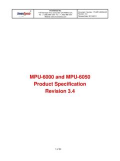
8 Charged devices and circuit boards can discharge without detection. Although this product FEATURES patented or proprietary protection circuitry, damage may occur on devices subjected to high energy ESD. Therefore proper ESD precautions should be taken to avoid performance degradation or loss of functionality. Page 6 of 21 Document Number: DS-INMP441-00 Revision: INMP441 SOLDERING PROFILE Figure 2. Recommended Soldering Profile Limits TABLE 5. RECOMMENDED SOLDERING PROFILE* PROFILE FEATURE Sn63/Pb37 Pb-Free Average Ramp Rate (TL to TP) C/sec max C/sec max Preheat Minimum Temperature (TSMIN) 100 C 100 C Minimum Temperature (TSMIN) 150 C 200 C Time (TSMIN to TSMAX), tS 60 sec to 75 sec 60 sec to 75 sec Ramp-Up Rate (TSMAX to TL) C/sec C/sec Time Maintained Above Liquidous (tL) 45 sec to 75 sec ~50 sec Liquidous Temperature (TL) 183 C 217 C Peak Temperature (TP) 215 C +3 C/ 3 C 260 C +0 C/ 5 C Time Within +5 C of Actual Peak Temperature (tP) 20 sec to 30 sec 20 sec to 30 sec Ramp-Down Rate 3 C/sec max 3 C/sec max Time +25 C (t25 C) to Peak Temperature 5 min max 5 min max *The reflow profile in Table 5 is recommended for board manufacturing with InvenSense MEMS microphones.
9 All microphones are also compatible with the J-STD-020 profile. tPtLt25 CTO PEAK TEMPERATUREtSPREHEATCRITICAL ZONETLTO TPTEMPERATURETIMERAMP-DOWNRAMP-UPTSMINTS MAXTPTLPage 7 of 21 Document Number: DS-INMP441-00 Revision: INMP441 PIN CONFIGURATIONS AND FUNCTION DESCRIPTIONS Figure 3. Pin Configuration TABLE 6. PIN FUNCTION DESCRIPTIONS PIN NAME FUNCTION 1 SCK Serial-Data Clock for I S Interface 2 SD Serial-Data Output for I S Interface. This pin tri-states when not actively driving the appropriate output channel. The SD trace should have a 100 k pulldown resistor to discharge the line during the time that all microphones on the bus have tri-stated their outputs. 3 WS Serial Data-Word Select for I S Interface 4 L/R Left/Right Channel Select. When set low, the microphone outputs its signal in the left channel of the I S frame. When set high , the microphone outputs its signal in the right channel. 5 GND Ground.
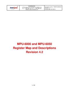
10 Connect to ground on the PCB. 6 GND Ground. Connect to ground on the PCB. 7 VDD Power, V to V. This pin should be decoupled to Pin 6 with a F capacitor. 8 CHIPEN Microphone Enable. When set low (ground), the microphone is disabled and put in power-down mode. When set high (VDD), the microphone is enabled. 9 GND Ground. Connect to ground on the PCB. 4L/R6 GND5 GND3WS7 VDD2SD8 CHIPEN1 SCK9 GNDBOTTOM VIEW(Notto Scale)Page 8 of 21 Document Number: DS-INMP441-00 Revision: INMP441 TYPICAL PERFORMANCE CHARACTERISTICS Figure 4. Frequency Response Mask Figure 5. Typical Frequency Response (Measured) Figure 6. Power-Supply Rejection (PSR) vs. Frequency 10 10 8 6 4 2024685010010kFREQUENCY (Hz)SENSITIVITY (dB)1k10 20 1001010010kFREQUENCY (Hz)AMPLITUDE (dB)1k0 8010010kFREQUENCY (Hz)PSR (dB)1k 10 20 30 40 50 60 70 Page 9 of 21 Document Number: DS-INMP441-00 Revision: INMP441 THEORY OF OPERATION The INMP441 is a high -performance, low-power, digital-output, omni-directional MEMS microphone with a bottom port.