Transcription of Electron Diffraction - Boston University Physics
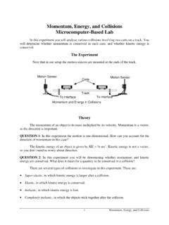
1 Electron Diffraction Do moving electrons display wave nature? To answer this question you will direct a beam of electrons through a thin layer of carbon and analyze the resulting pattern. Theory Louis de Broglie originated the idea that moving electrons may exhibit both particle and wave nature. He proposed that, analogous to photons, the wavelength of the Electron is given by: = hp = hmv (1) where h is Planck's constant and p = mv is the nonrelativistic Electron momentum. This experiment is an attempt to see whether electrons really do act like waves or whether they always act like particles. If electrons behave as particles (rigid spheres), the distribution of electrons will vary continuously as a function of angle as in Figure 1.
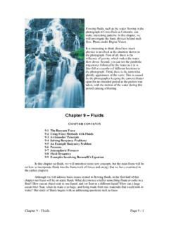
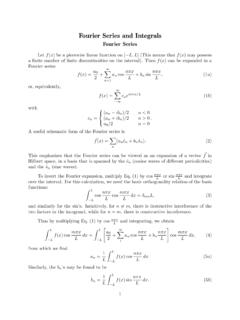
2 This distribution will vary only slightly with changes in Electron energy. Electron beamcarbon targetI( ) Figure 1. Particle Model Diffraction . Continuous distribution of electrons as a function of angle. If electrons behave as a wave, however, a Diffraction pattern will emerge. We can make an analogy with the Diffraction of x-rays by a crystal. 17 Electron Diffraction Review of x-ray Diffraction Crystals act as three-dimensional gratings; they scatter the wave and produce observable interference effects. In fact, x-rays scatter from the lattice planes (or Bragg planes) of the crystal as shown in Figure 2.
3 Figure 2. Electron Waves Reflected from Atomic Planes. There are two conditions for constructive interference of waves: 1. The angle of incidence must equal the angle of reflection 2. The difference in path length must be an integral number of wavelengths n = 2 d sin . Bragg s Law (2) where n is an integer and is the order of Diffraction . By looking at the Diffraction pattern and calculating the angle of Diffraction , Bragg s Law allows us to determine either: the wavelength of the x-rays if the crystal structure is known, or the interatomic spacing of the crystal if the x-ray wavelength is known. The second method is often used to determine the structure of an unknown crystal by performing an x-ray Diffraction experiment. If electrons act like waves, we should be able to apply Bragg s Law to the Diffraction of electrons. In that case the beam would appear as concentric rings around a bright 18 Electron Diffraction center.
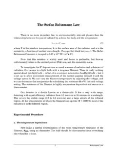
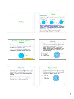
4 This pattern can be thought of as a one-dimensional Diffraction pattern of bright spots rotated about its center. Electron beam carbon target I( ) Figure 3. Wave Model Diffraction . Constructive interference of an Electron beam through a polycrystal. The Experiment This experiment involves directing a beam of electrons through a carbon target, scattering the electrons, and analyzing the pattern produced on a luminescent screen. APPARATUS THE Electron GUN The heater, cathode, and anode make up the Electron gun. Electrons are produced by heating a filament that is located inside an oxide-coated metal can called the cathode. Electrons are ejected by thermionic emission from this heated piece of metal (see Figure 4). Once emitted, the electrons are accelerated by two pairs of anode rings. You apply an adjustable acceleration potential Va (2000-4000 V dc) with the kilovolt power supply between the cathode (-) and anode (+).
5 This accelerates electrons to form an Electron beam. The beam will have kinetic energy equal to the change in electric potential energy (eVa ). If the beam velocity is non relativistic (eVa<<mc2), we have at the anode: 12 mv 2 = eVa (3) CARBON TARGET As the Electron beam passes into the anode, it strikes a very fine nickel screen which holds vaporized graphite (carbon). The carbon suspension acts as a polycrystal, 19 Electron Diffraction which means that the carbon consists of a large number of microcrystals that are randomly oriented.
6 This allows us to sample all possible angles of incidence without changing the direction of the Electron beam. If electrons act like a wave, different atomic planes will produce constructive interference and the resulting Electron Diffraction pattern will consist of concentric rings one for each plane that satisfies the Bragg s Law for constructive interference, as in Figure 3. If electrons act like particles the pattern will be as shown in Figure 1. Diffraction caused by the nickel mesh may be neglected. LUMINESCENT SCREEN After leaving the target, diffracted electrons travel a certain distance (L) and strike a phosphor screen. The screen is excited by the electrons, allowing you to see the pattern made by the scattered electrons. Since the screen is inside a sphere, you should use a flexible ruler to take measurements off the screen.
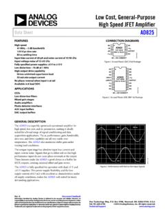
7 Procedure Use the following diagram to connect the Electron Diffraction tube to its power supplies. R cathodeanodeheater carbon targetScreen V ac 2 mm plug 0-5000 V dcVa5 kV POWER SUPPLYG7F3 F4 C5 +-Figure 4. Electron Diffraction Experiment Diagram. CONNECTIONS Make sure all power is off (all equipment) before making any connections. Connect the Electron Diffraction tube to the power supply as shown. 20 Electron Diffraction er Connect the multimeter (ammeter) between the anode and the positive side of the high voltage power supply. Set the multimeter to its current scale (mA) and turn it on. Make sure the high voltage supply is set to its minimum.
8 Turn on the power and wait for one minute for the cathode to reach a stable temperature. CONTROLLING THE CURRENT Normal operating current should be kept between to mA during measurements, and the voltage should be kept below kV. Higher currents can damage the carbon target. If it becomes necessary to exceed these levels, make your measurements quickly and decrease the voltage as soon as you obtain your results. DO NOT EXCEED mA current. Slowly increase the high voltage until you observe a pattern (around 2000 volts). Monitor the current closely. Questions Pre-laboratory assignment 1. Geometric analysis Using the Figure 5 below, find a geometric relation between D, L and angle in triangle OAB. You may assume that the angle is small. carbon target LAD/2Bo 2. Express the wavelength of the Electron as a function of the accelerating potential Va -- using the de Broglie relation (1) and relation (3).
9 3. Express the wavelength of the Electron as a function of -- using Bragg s relation (2). Be sure to keep in mind the relation between and . 21 Electron Diffraction 4. Equate the wavelength in questions 2 and 3 and solve for D. Show that D is proportional to 1/Va . MEASUREMENTS First observe whether the pattern of scattered electrons is consistent with particle behavior or wave behavior. If you observe any rings on the screen take readings of the accelerating voltage versus ring diameters for each ring observed. Measure the diameter arc length (diameter bent around the screen) using a flexible, transparent ruler.
10 Start at the minimum voltage and record diameters and voltages at kV increments for each ring observed. V 1st D 2nd D 3rd D At voltages above 4 kV, make each reading quickly and decrease the voltage to zero as soon as you are finished. 22 Electron Diffraction Analysis 1. Make a plot of 1/Va versus D for each ring. Does a straight line fit your data? If so, use the value of the slope to calculate the plane separation d that corresponds to each ring (use question 4 from the pre-laboratory assignment). The length L is given to be L= 2. If the crystal structure of carbon is cubic, what would be the spacing of the atoms?