Transcription of FIGURE 1: SINGLE POLE WIRING DIAGRAM FIGURE 1: SCHÉMA …
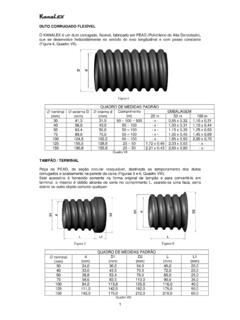
1 FIGURE 1: SINGLE POLE WIRING DIAGRAM . SAL06B-PTA (REV. A) FIGURE 1: SCH MA DE C BLAGE DE UNIPOLAIRE. ENGLISH IN : Cooper WIRING Devices, 203 Cooper Circle, Peachtree City, GA 30269 866-853-4293. FIGURA 1: DIAGRAMA DE CABLEADO UNIPOLAR. Green or Bare/Vert ou nu/Verde o desnudo SAL06P - ALL LOAD DIMMER, SINGLE POLE/3-WAY - 120V/AC, 60 Hz - 300W DIMMABLE LED/CFL - 600W INC/DIMMABLE ELV/HALOGEN - 600W DIMMABLE FLUORESCENT - 600VA MLV - For use with listed LED and CFL lamps TOP. SPECIFICATIONS: Black Thumbwheel BK Black/Noir/Negro Hot/Phase/Fase For dimmable LED/CFL, Incandescent (INC), Magnetic Low Voltage (MLV), Electronic Low Voltage (ELV), Halogen or dimmable fluorescent light fixtures. CFL/LED - 300W Noir Molette Slider Incandescent, Electronic Low Voltage, and Halogen - 600W Negro Ruedecilla Glissi re Fluorescent - 600W. Magnetic Low Voltage - 600VA YL Deslizador Multigang applications allowed at above ratings.
2 Line/Ligne/Linea WARNINGS AND CAUTIONS: Turn circuit breaker to OFF position or remove fuse(s) and test that power is off before installation process. Never wire any electrical device with power turned on. WIRING dimmer HOT may cause permanent damage 120V AC - 60 Hz to this device and other equipment and void warranty. Must be installed and used in accordance with all national and local electrical codes. To reduce the risk of overheating and possible damage to this device or other equipment, do not install to control a receptacle, motor-operated appliance, or a transformer-supplied appliance. Use with permanently installed fixtures, and listed 120V/AC dimmable lamp types. Load/Chargement/. Mixing CFL and LED lamps on the same dimming circuit may result in less than optimal lighting performance. Only one dimmer can be used in a 3-way circuit. The switch on the other end will turn on at the brightness level selected at the dimmer.
3 Carga White/Blanc/Blanco Neutral/Neutre/. Do not exceed maximum rating of dimmer as indicated on the device. For new installations, install a test switch before installing the dimmer, to verify proper lighting circuit operation. Neutro If a bare copper or green ground connection is not available in the wallbox, contact a licensed electrician for installation. Use only #14 or #12 copper wire rated for at least 75 C with these devices. DO NOT USE WITH ALUMINUM WIRE. It is normal for the dimmer to feel warm during operation. Tools needed for Installation: Screwdriver (Slotted/Phillips) Pliers Electrical tape Cutters Determine what type of installation it is and follow the corresponding installation instructions below. SINGLE -pole installation controls light from one location. 3-way installation controls light from two locations. Turn off power. Remove wallplate. SINGLE -POLE INSTALLATION: 1.
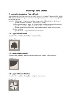
4 Disconnect the existing switch, and connect dimmer as per FIGURE 1 SINGLE -Pole WIRING DIAGRAM . FIGURE 2: 3-WAY WIRING DIAGRAM . 2. Connect one of the wires of the switch to the Black screw. 3. Connect the other wire from the switch to one of the Yellow screws. NOTE: One of the Yellow screws is covered by a white label, and is not required for a SINGLE -pole installation. FIGURE 2: SCH MA DE C BLAGE DE 3-VOIES. 4. Connect the ground wire to the Green screw. FIGURA 2: DIAGRAMA DE CABLEADO DE 3-VIAS. 5. Insert the dimmer switch into the electrical box and attach with mounting screws provided. NOTE: Make sure the word TOP is facing up on the dimmer as shown in FIGURE 1. Green or Bare/Vert ou nu/Verde o desnudo 3-WAY INSTALLATION: NOTE: One dimmer can be installed in either switch location, however, you cannot put a dimmer in both locations. 1. Select the 3-way switch to be replaced by the dimmer.
5 This will typically be the location that you would normally want to control the dim level. Black Thumbwheel TOP. 2. Tag the common wire. The wire connected to the Common terminal is identified by a marking indicating BK , or the screw color is Black, and is different than the other two screws. Noir Molette 3. Disconnect the 3-way switch that will be replaced by the dimmer. 4. Connect the dimmer as show in FIGURE 2 3-Way WIRING DIAGRAM . Negro Ruedecilla Tag/Etiquette/Marca 5. Connect the tagged common wire to the Black screw on the dimmer. BK 3-WAY YL DIMMER BK. 6. Connect one of the wires from the switch to one of the two Yellow screws and connect the other wire from the switch to the other Yellow screw. SWITCH Hot/Phase/Fase 7. Connect the Ground wire to the Green screw. Black/Noir/Negro 8. Insert the dimmer switch into the electrical box and attach with mounting screws provided.
6 NOTE: Make sure the word TOP is facing up on the dimmer as shown in FIGURE 2. Travellers Slider MINIMUM DIMMING LEVEL: YL YL YL. A complete list of approved dimmable CFL and LED lamps is provided with this dimmer. The factory setting for the dimming level allows the dimmer to be used with a wide range of CFL and LED lamps. Some CFL and Navettes Glissi re LED lamps can be dimmed lower than the dimmer's default factory setting. It is recommended to install the dimmer and check the performance of lamps at default factory setting. To optimize the lower end dimming Cursor Line/Ligne/Linea range for a particular CFL/LED lamp, see DIMMING LEVEL ADJUSTMENT section below. Deslizador NOTE: It is normal for the lights to momentarily turn ON at full brightness when power up to ensure all lights start properly at low dim levels. 120V AC - 60 Hz DIMMING LEVEL ADJUSTMENT: INTERRUPTEUR 3-VOIES GRADATEUR.
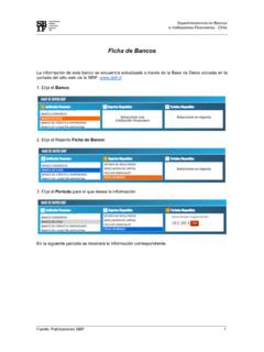
7 1. Do not install the wallplate. Restore power by turning ON the circuit breaker or reinstalling the fuse. Turn ON the dimmer and lower the dimmer slider to minimum (the bottom of the travel). INTERRUPTOR 3-VIAS REDUCTOR. 2. Rotate the dimming level adjustment thumbwheel DOWN until the lowest stable light level is achieved. (See Fig. 3) Load/Chargement/. 3. If the light flickers, rotate the thumbwheel UP to achieve a stable light output. 4. Turn the dimmer off for 30 seconds, then back on to verify if the lamp turns ON at desired setting. If lamp does not turn ON, rotate the thumbwheel UP and repeat this step. After dimming level adjustment is completed, Carga White/Blanc/Blanco install the wallplate. Neutral/Neutre/Neutro NOTE: All CFL and LED lamps have different dimming range and vary with bulb type, manufacturer and may not achieve the same lower dimming level as incandescent or halogen lamps.
8 It is also noted that unlike incandescent lights, there is no change in the color of light when CFL or LED lamps are dimmed. There is a change only in the light output level when dimmed. TROUBLESHOOTING. If you have a problem with your dimmer, first follow this guide. If the problem persists, call the customer service hotline at 1-866-853-4293 between 8 and 6 EST weekdays. Symptoms Possible Solution If the light does not turn ON 1. Check to see if circuit breaker or fuse(s) has tripped. 2. Check to see if lamp is burned out. If lights are flickering 1. Check if lamp has a bad connection. 2. Check if wires are not secured firmly under terminal screws of dimmer and/or 3-way switch (if installed). Lights flicker or turn OFF at low dim level setting 1. Dim level adjustment set too low. Rotate the dimmer level thumbwheel UP. FIGURE 3: DIMMING LEVEL ADJUSTMENT. Lights momentarily bright at turn ON This is a normal feature that ensures all lights start properly at low dim levels.
9 FIGURE 3: R GLAGE DU NIVEAU D'ATT NUATION. FIGURA 3: AJUSTE DEL NIVEL DE ATENUACI N. COOPER WIRING DEVICES LIMITED 2 YEAR WARRANTY. Cooper WIRING Devices (CWD) warrants its Smart Dimmer System to be free of defects in materials and workmanship in normal use and service for a period of two years from date of original purchase. THIS TWO (2) YEAR LIMITED WARRANTY IS IN LIEU OF ALL OTHER. WARRANTIES, OBLIGATIONS, OR LIABILITIES, EXPRESSED OR IMPLIED (INCLUDING ANY IMPLIED WARRANTY OF MERCHANTABILITY OR FITNESS FOR A PARTICULAR PURPOSE THAT IS IN DURATION IN EXCESS OF TWO YEARS FROM THE DATE OF ORIGINAL CONSUMER. UP/HAUT/HACIA ARRIBA. PURCHASE). NO AGENT, REPRESENTATIVE, OR EMPLOYEE OF CWD HAS AUTHORITY TO INCREASE OR ALTER THE OBLIGATIONS OF CWD UNDER THIS WARRANTY. To obtain warranty service for any properly installed CWD Smart Dimmer System that proves defective in normal use send the defective Smart Dimmer System prepaid and insured to Quality Control Dept.
10 , Cooper WIRING Devices, 203 Cooper Circle, Peachtree City, GA 30269; in DOWN/BAS/HACIA ABAJO. Canada: Cooper WIRING Devices, 5925 McLaughlin Road, Mississauga, Ontario L5R 1B8. CWD will repair or replace the defective unit, at its option. CWD will not be responsible under this warranty if examination shows that the defective condition of the unit was caused by misuse, abuse, improper installation, alteration, improper maintenance or repair of damage in shipment to CWD. CWD SHALL HAVE NO RESPONSIBILITY FOR INSTALLATION OF THE SMART DIMMER SYSTEM, OR FOR ANY PERSONAL INJURY, PROPERTY DAMAGE, OR ANY SPECIAL, INCIDENTAL, CONTINGENT, OR CONSEQUENTIAL DAMAGES OF ANY KIND, RESULTING FROM DEFECTS IN THE SMART DIMMER SYSTEM OR FOR BREACH OF ANY EXPRESS OR IMPLIED WARRANTY ON THIS PRODUCT. THE EXCLUSIVE REMEDY FOR BREACH OF THE LIMITED WARRANTY CONTAINED HEREIN IS THE REPAIR OR REPLACEMENT OF THE DEFECTIVE PRODUCT AT CWD'S OPTION.