Transcription of Finite Element Analysis in 2D and 3D Models for …
1 2006 ABAQUS Users Conference 329 Finite Element Analysis in 2D and 3D Models for sound and restored Teeth Andr a B. Motta*, Luiz C. Pereira** and Andr ia da Cunha** *Dentist, MSc. in Oral Rehabilitation and Doctoral student of the Biomaterials Group, Department of Metallurgy and Materials Engineering, Federal University of Rio de Janeiro, Brazil. **DSc., Professor of the Department of Metallurgy and Materials Engineering, Federal University of Rio de Janeiro, Brazil. **Dentist, MSc. and Researcher of the Biomaterials Group, Department of Metallurgy and Materials Engineering, Federal University of Rio de Janeiro, Brazil. Abstract: Finite Element Analysis (FEA) was first used in Dentistry in the 70 s to replace photoelasticity tests. Since then, many researches have been developed by association of dentists and engineers, using 2D Models . Because of the development of new image acquisition techniques and the development of technical design program the use of 3D Models has increased.
2 It is difficult to analyze the mechanical behavior of sound or restored teeth using laboratorial or in vivo methods because many variables interplay: geometry complexity, different materials involved and different load modes, little availability of extract teeth and patient participation. FEA allows the creation of complex Models and the Analysis of each variable s influence on a model constructed by the researcher, which has more significant geometric elements . The Analysis already done by our group TerMic/Biomaterials from PEMM/UFRJ includes stress distribution Analysis of 2D Models with different modes of load on teeth in different conditions: sound , with an abfraction lesion, direct restoration (amalgam and composite resin) and indirect restoration (dental crown or fixed partial prosthesis). Nowadays our group is developing 3D Models to verify the volumetric/geometric implications in results. sound and abfraction teeth 3D Models had already been done and now we are analyzing the main differences between 3D and 2D Models .
3 Validation of the results is provided by in vitro mechanical tests using extracted teeth. Keywords: 2D/3D Tooth Design, Abfraction, Dentistry, Enamel anisotropy, Metal-ceramic restorations. 330 2006 ABAQUS Users Conference 1. Introduction Finite Element Methods (FEM) analyses have been widely used in engineering since the 60s. They are an important tool in the understanding of the mechanical behavior of materials used in Industry. However, in Dentistry this kind of Analysis is rather recent. Although the first article published by FARAH et al. on the subject dates back to 1973, this technique is still little used. That is mainly due to (i) the difficulty associated with the Models elaboration, for they present different shapes depending on the tooth to be analyzed, and (ii) to the difficulty involved in obtaining the mechanical properties of the tooth s constituent materials: enamel, dentin, cementum, pulp, spongy bone, compact bone and periodontal ligament.
4 Furthermore, little is known about the contact areas between such materials and their degree of influence on the mechanical behavior of the tooth as a whole. FEM enables analyses of both sound and restored teeth. The restorations may be direct, when inserted directly by the dentist, or indirect, when the restoration itself is made at a laboratory and later cemented to the patient s tooth. For each kind of restoration, different types of materials are employed. The most commonly used materials for direct restorations are composite resin and amalgam. For indirect restorations, metal alloys, metals and ceramics, all-ceramic and fiber-reinforcement resins. Even though there are many variables to be considered, the FEM analyses allow the manipulation of one parameter only, making it possible to analyze that parameter influence on the mechanical behavior in general. This is a difficult task to achieve through in vitro trials and impossible through in vivo analyses. Those types of Analysis are usually carried out by using statistic data, which demands a great number of samples and long trial periods.
5 The aim of this paper is to describe the analyses of stress distribution and fracture behavior in sound and restored teeth using FEM techniques and ABAQUS program. 2. Technique development The Models for the stress and fracture behavior analyses by FEM in two and three dimensions (2D/3D) were created from images of natural teeth of different types: incisive, canine, premolar and molar. 2D model A natural tooth selected was inserted into an epoxy resin (#331, Epoxtec, RJ, Brazil) and longitudinally abraded up to mesial-distal half distance. Sequential measurements were taken so as to allow for a correct and precise identification of the abrasion plane. This plane was analyzed on stereoscopic microscope (Nikon, model 102) and digitally photographed (Nikon Coolpix 950), always using a scale for the dimensional calibration of the digital images. Those digital images were exported to a vectorial drawing software (AutoCad 2000, Autodesk Inc., Neufchatel, Switzerland).
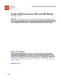
6 The outline of enamel, dentin and pulp was designed over the real model . Dental 2006 ABAQUS Users Conference 331 cavities, restorations and lesions were also designed. The surrounding dental tissues were designed according to their normal anatomy described in literature. For the periodontal ligament, it was assumed a thickness of mm (Rees, 2003) and a distance of mm from the ridge alveolar bone to the cementum-enamel junction (Lindhe, 1999) (Figure 1). Figure 1. Outlines of dental structures designed over the natural tooth. Each part was exported to the FEM Analysis program (ABAQUS CAE version , Hibbit Inc., Rhode Island, USA). All structures were considered homogeneous solids and their mechanical properties (modulus of elasticity and Poisson s ratios) are described in Table 1. Tabel 1. Mechanical properties used for the structures of 2D and 3D Models . Material Elastic Modulus (E) (MPa) Poisson s ratio ( ) Isotropic Enamel (Rees, 2003) 80000 Anisotropic Enamel (Rees, 2003) E12 = 80000 E13 = E23 = 20000 12 = 13 = 23 = Dentin (Toparli, 2002) 18600 Cementum (Toparli, 2002) 18600 Dental Pulp (Rees, 2003) Periodontal Ligament (Rees, 2003) 50 Spongy Bone (Rees, 2003) 345 Compact Bone (Toparli, 2002) 13800 Composite Resin (Ensaff, 2001) 10000 Ceramic (Ibrahim, 2004) 68900 Ni-Cr Alloy (Toparli, 2002) 205000 FZn Luting Agent (Lanza, 2005) 22000 In most of the analyses the mechanical properties were considered isotropic.
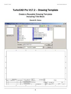
7 Yet the enamel was constituted of hydroxyapatite crystals organized as prisms which characterized it as anisotropic material (Habelitz, 2001). For the anisotropic analyses, partitions were created in enamel in accordance with the orientation changes of prisms. Coordinate axes were defined in order to determine the main direction of each partition (Figure 2, axis x). Depending on the type of Analysis , the encastre was positioned in different locations. When compact bones were present, the encastre was made on their base line. Otherwise the encastre was made on the base line of the outlined model . The Models were fixed to prevent rotation and translation during load application. 332 2006 ABAQUS Users Conference Figure 2. Dental enamel partitions. Paths created to graphs plot. The mesh applied to the Models was of 4-node quadrilateral elements which led to liable results. The mesh size was defined differently for each constituent of the model according to the specific necessities to obtain less distortion.
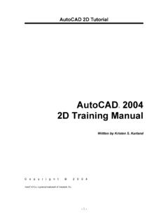
8 The assessment of the mesh was done using a specific tool from ABAQUS program (Figure 3). The mesh refinement was realized in specific areas of the analyses, considered ideal when the stress values found did not present significant differences. Figure 3. Mesh applied to a metal-ceramic full crown in 2D model of a premolar tooth. Load conditions to which the Models were submitted must follow the specific interests of the analyses in accordance with the real situations happening in oral cavities. The functioning of the teeth in oral cavities depends on some factors: a) Tooth position on the dental arch: loads in the anterior region are lower than in the posterior regions because the resultant of the occlusal loads is located in the area next to temporomandibular join. In a functional occlusion loads in the posterior region are in vertical direction. For that reason, during the occlusion only the posterior teeth touch, and during the mandibular movements only the anterior teeth touch.
9 When there is nonfunctional occlusion some posterior teeth may touch during the mandibular movements producing loads in horizontal directions. This fact represents a risk of lesions in the teeth and surrounding tissues (Okeson, 2003). 2006 ABAQUS Users Conference 333 b) Food type: food of rigid consistency transmits more stress to opposing teeth considering the same masticatory load. DEJAK et al. (2003) using FEM in molars teeth found that the maximum stresses occur on the occlusal enamel during the mastication of food with higher modulus of elasticity. The authors found that the least favorable condition was with non homogeneous food (material of low modulus mixed with small fragments of bone). c) Parafunction: parafunction is characterized by the use of oral cavity structures out of their normal function. Bruxism and tooth clenching cause damages to teeth and surrounding tissues with high indexes of orofacial pain.
10 In those parafunctions the loads applied on the teeth increase significantly and the protection system of oral cavity is not active (Okeson, 2003). The loading values used for the analyses range from 100N to 800N (Ferrario, 2004). The first value is in accordance with the average values found in literature for occlusal forces during physiological function. The last value is related to the average values measured during the parafunctional activity (non-physiological function). It is important to highlight that those values correspond to local compressive loads (contact). The second parameter to be considered is the angle of the applied load related to the contact area plane. The individual contact in each cusp region leads to the decomposing of that load in horizontal and vertical force vectors. The measurement of cusp inclination in the teeth Models was realized in the Image-Pro Plus (Media Cybernetics, USA) program. In physiological situations the local load application must be simultaneous on the two cusps (Figure 4).