Transcription of Fisher 2100 Pneumatic and 2100E Electric Liquid Level …
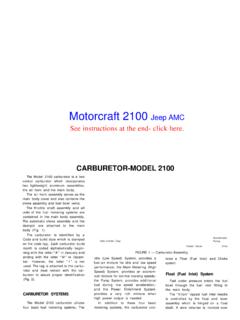
1 Instruction Manual 2100 and 2100E Liquid Level Switches D200119X012 July 2018. Fisher 2100 pneumatic and 2100e electric liquid level Switches Contents Figure 1. Fisher 2100 Pneumatic Liquid Level Switch Introduction .. 1. Scope of Manual .. 1. Description .. 2. Specifications .. 2 APPROXIMATE. Educational Services .. 4 SWITCHING POINT. Installation .. 4. Hazardous Area Classification Information and Safe Use Instructions .. 4. Installation Procedures .. 6. Common Procedures for Either Switch .. 6. Additional Procedures for 2100 Switch .. 6. Additional Procedures for 2100E Switch .. 7. Calibration Check .. 8. Principle of Operation .. 9. Maintenance .. 10. Operational Test .. 10. 2100 Switch Maintenance Procedure .. 12. 2100E Switch Maintenance Procedure .. 13. Parts Ordering .. 14. Parts Kits .. 14. Parts List .. 15. Introduction Scope of Manual This instruction manual includes installation, maintenance, and parts information for the 2100 Pneumatic and 2100E .
2 Electric Liquid Level switches. Refer to separate instruction manuals when you require information regarding related valves, actuators, positioners, and accessories. Do not install, operate or maintain a 2100 Pneumatic or a 2100E Electric Liquid Level switch without being fully trained and qualified in valve, actuator and accessory installation, operation and maintenance. To avoid personal injury or property damage it is important to carefully read, understand, and follow all of the contents of this manual, including all safety cautions and warnings. If you have any questions about these instructions, contact your Emerson sales office or Local Business Partner before proceeding. 2100 and 2100E Liquid Level Switches Instruction Manual July 2018 D200119X012. Description The on off 2100 Pneumatic switch (figure 1) and the 2100E Electric switch (figure 2) operate shutdown valves or alarm systems when Liquid in a vessel reaches a predetermined Level .
3 The 2100 switch uses an externally mounted displacer that operates a nozzle flapper to vent the supply pressure when the switch is activated. The nozzle flapper has a soft seat for tight shutoff when the switch is in its normal position (flapper against the nozzle). The 2100E switch uses the displacer torque to activate and deactivate an Electric switch for positive on off service. The displacer on each type can withstand up to 1 1/2 times the maximum working pressure, allowing it to remain in the cage during hydrostatic testing. Unless otherwise noted, all NACE references are to NACE MR0175-2002. Figure 2. Fisher 2100E Electric Liquid Level Switch APPROXIMATE. SWITCHING POINT. X0682. Specifications Specifications for the 2100 and 2100E switches are shown in table 1. WARNING. This product is intended for a specific current range, temperature range and other application specifications. Applying different current, temperature and other service conditions could result in malfunction of the product, property damage or personal injury.
4 2. Instruction Manual 2100 and 2100E Liquid Level Switches D200119X012 July 2018. Table 1. Specifications Input Signal Displacer Diameter Liquid Level 102 mm (4 inches). Minimum Process Liquid Specific Gravity Process Connection Size (consult your Emerson sales office or Local 153 Bar (2220 psig) WOG(3): J 1 NPT internal Business Partner for specific gravity below this value) J DN 50 (NPS 2) Schedule 80 buttwelding ends, or J DN 50 (NPS 2) Schedule 160 buttwelding ends Output Signal 2100 Switch: Output equal to supply pressure when 2100 Switch Supply Pressure Connection Size the switch is in the normal position (flapper against 1/4 NPT internal nozzle). Output reduced to approximately atmospheric pressure, depending upon size of the 2100E Switch Electrical Connection Size bleed orifice and piping configuration, when the switch is activated 1/2 NPT external 2100E Switch: Same as supply signal Hazardous Area Classification for 2100 Switch Supply Signal The 2100 Pneumatic switch complies with the 2100 Switch: J to bar (30 to 60 psig), J requirements of ATEX Group II Category 2 Gas and to bar (60 to 100 psig), or J to bar (100 Dust to 150 psig).
5 2100E Switch: 11 amperes, 1/4 horsepower at 125/250 volts AC; 5 amperes resistive, 3 amperes Hazardous Area Classification for 2100E Switch inductive at 28 volts DC. CSA, FM, ATEX, IECEx, UL, CUTR. Supply Medium (2100 Switch) Refer to Hazardous Area Classifications and Special Air or Natural Gas Instructions for Safe Use and Installations in Hazardous Location on page 4. Steady State Air Consumption(1) (2100 Switch) Contact your Emerson sales office or Local Business Less than normal m3/hr ( scfh) for all supply Partner if additional information is required. pressures when the Liquid Level is mm (1 inch). below the normal switch position (flapper against Shipping Weight nozzle) for high Level switching or mm (1 inch) kg (38 pounds). above the normal switch position for low Level switching Declaration of SEP. Maximum Working Pressure(2) Fisher Controls International LLC declares this J 153 bar (2220 psig) WOG(3) except J 24 bar product to be in compliance with Article 3 paragraph (350 psig) WOG is the maximum working pressure for 4 of the PED Directive 2014/68/EU.
6 It was designed sight window construction and manufactured in accordance with Sound Engineering Practice (SEP) and cannot bear the CE. marking related to PED compliance. Operative Temperature Range(2). However, the product may bear the CE marking to 2100 Switch: - 29 to 204_C (- 20 to 400_F) indicate compliance with other applicable European 2100E Switch: - 29 to 82_C (- 20 to 180_F) Community Directives. NOTE: Specialized instrument terms are defined in ISA Standard - Process Instrument Terminology. 1. Normal m3/hr normal cubic meters per hour (0_C and bar, absolute); scfh standard cubic feet per hour (60_F and psia). 2. Pressure and temperature limits in this document and any applicable standards or code limitations should not be exceeded. 3. Water, Oil, Gas maximum working pressure rating. Corresponds to Cold Working Pressure: the maximum pressure rating allowed under normal ambient temperature conditions, which are usually understood to be - 29_C to 38_C (- 20_F to 100_F).
7 Refer to MSS SP 25. 3. 2100 and 2100E Liquid Level Switches Instruction Manual July 2018 D200119X012. Educational Services For information on available courses for 2100 pneumatic and 2100e electric liquid level switches, as well as a variety of other products, contact: Emerson Automation Solutions Educational Services - Registration Phone: 1-641-754-3771 or 1-800-338-8158. E-mail: Installation WARNING. Always wear protective clothing, gloves, and eyewear when performing any installation operations to avoid personal injury. Check with your process or safety engineer for any additional measures that must be taken to protect against process media. If installing into an existing application, also refer to the WARNING at the beginning of the Maintenance section in this instruction manual. Hazardous Area Approvals and Special Instructions for Safe Use and Installations in Hazardous Locations 2100E Electrical Switch Component Inspect the electrical switch component in your 2100E Electric Liquid Level switch to determine the part number of the switch component, if specified.
8 Contact your Emerson sales office or Local Business Partner if additional information is needed. CSA Class I, Division 1, Groups A, B, C, and D; Class II, Division 1, Groups E, F, and G ; Dual Seal FM XP Class I, Division 1, Groups A, B, C, D T6; DIP Class II, Division 1, Groups E, F, G T6; IP66. Special Conditions of Use: Model 057-0770 has temperature classification T5 for 11 Amp and T6 for 5 Amp Ambient temperature: 11 A, Ta = 75_C ; 5 A, Ta = 70_C. Model 057-0771 has temperature classification T4 for 11 Amp and T6 for 5 Amp Ambient temperature: 11 A, Ta = 65_C ; 5 A, Ta = 70_C. 4. Instruction Manual 2100 and 2100E Liquid Level Switches D200119X012 July 2018. ATEX II 2 G D. IECEx Ex d IIC T4/T5/T6 Gb ; Ex tb IIIC Txx_C Db Model 057-0770: Gas Ex d IIC T6 (Ta = -40_C to +70_C) (5 A Max) ; Ex d IIC T5 (Ta = -40_C to +75_C) (11 A Max). Dust Ex tb IIIC T85_C Db IP6X (Ta = -40_C to +70_C) (5 A Max) ; Ex tb IIIC T100_C Db IP6X (Ta = -40_C to +75_C).
9 (11 A Max). Model 057-0771: Gas Ex d IIC T6 (Ta = -40_C to +70_C) (5 A Max) ; Ex d IIC T4 (Ta = -40_C to +65_C) (11 A Max). Dust Ex tb IIIC T85_C Db IP6X (Ta = -40_C to +70_C) (5 A Max) ; Ex tb IIIC T135_C Db IP6X (Ta = -40_C to +65_C). (11 A Max). Special Conditions for Safe Use: Each Electrical Snap-Switch Assembly shall be installed such that the equipment wiring is protected from mechanical damage. The equipment wiring must not be subjected to tension or torque. If it is to be terminated within a potentially explosive atmosphere, a suitably certified termination facility must be used. UL Class I Division 1 Groups A,B,C,D ; Class II Division 1 Groups E,F,G. 2100E Electric Switch Assembly Customs Union (Russia, Belarus, Kazakhstan and Armenia) Certificate number TC RU C-US.ГБ ; 1Ex d IIC. T4/T5/T6 X, IP66. Ambient Temperature: T4 DPDT, 11 A maximum current, -40 to 65_C. T5 SPDT, 11 A maximum current, -40 to 75_C. T6 SPDT and DPDT, 5 A maximum current, -40 to 70_C.
10 Conditions of Application 1. Level switch type 2100E should be used according to the given Ex-marking, requirements of CU TR 012/2011, GOST (IEC 60079-14:1996), current Electrical plant arrangement rules (PUE, art. ), Technical maintenance rules for electrical plants (PTEEP, art. ), other normative documents regulating application of electrical equipment in explosive areas, and manufacturer's instruction manual. 2. Potential Ex application areas of Level switch, categories and groups of explosive gas and vapors mixtures with air according to requirements of GOST (IEC 60079-10:1995), GOST (IEC. 60079-12:1978) and Electrical plant arrangement rules (PUE, art. ). 3. Level switch must be used with approved cable glands and plugs that provide the required type and Level of protection and ingress protection. 4. Sign X after the Ex mark means that the electrical switch type 057-07 ** as part of an electronic module comprising a Level switch comes with a permanently attached cable.