Transcription of Fisher 846 Electro-Pneumatic Transducer - Emerson Electric
1 846 Electro-Pneumatic TransducerThe Fisher 846 Electro-Pneumatic Transducer is arugged, field-mountable Transducer that accepts anelectrical input signal and converts it to a pneumaticoutput signal. Typically, the 4 to 20 mA is converted to bar (3 to 15 psi). In the most commonapplication, the Transducer converts an electricaloutput signal from a controller to a pneumatic signalnecessary to operate a control valve actuator orpneumatic Transducer includes a deflector/nozzle design(figure 1) that consists of two nozzles positioned sothat the constant air flow exiting the supply nozzle isdirected at the entrance of the receiver nozzle.
2 Eachnozzle has a large bore of mm ( inches),which provides good resistance to plugging. The inputcurrent signal positions a deflector bar within thenozzle's flow stream. As the input signal changes, thedeflector bar moves to alter the flow stream to thereceiver nozzle, establishing a pilot pressure at thereceiver nozzle. The pilot pressure, in turn, controls thebooster stage and output of the electronic feedback control network constantlycompares the value of the pneumatic output signalwith the input current signal. A solid-state pressuresensor is part of the electronics package monitoringthe pneumatic output (figure 3).
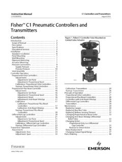
3 A comparator circuitin the control network detects input-output deviationsand adjusts the output by moving the deflector in thepilot stage to a corrected position. Because of thisfeedback network, the Transducer can correct forerror-producing effects such as variations in supplypressure and downstream MOUNTEDON Fisher 667 ACTUATORFISHER 846 Electro-Pneumatic TRANSDUCER846 TransducerD102127X012 Product :846 September 2017846 TransducerD102127X012 Product :846 September 2017 2 SpecificationsInput Signal4-20 mA DC, field adjustable split CircuitSee figure 4 Output SignalStandard Performance: to bar (3 to 15 psi).
4 Rangeability between to bar (1 and 18 psi)Multirange Performance: J0 to bar (0 to 18 psi), to bar (6 to 30 psi), and J0 to bar (0 to33 psi) nominal ranges. Actual rangeability availablebetween to bar ( and 33 psi)Action: JDirect (increasing input signal increasestransducer output) (Minimum span, 6 psi) orJReverse (increasing input signal decreasestransducer output) (Minimum span, 11 psi)Supply PressureStandard Performance: to bar (18 to 24 psi)Multirange Performance:Minimum: bar (3 psi) [ bar (2 psi) for a bar(33 psi) output] greater than the maximum calibratedoutput.
5 Bar (35 psi)Supply Pressure MediumClean, dry airPer ISA Standard maximum 40 micrometer particle size in the airsystem is acceptable. Further filtration down to 5micrometer particle size is recommended. Lubricantcontent is not to exceed 1 ppm weight (w/w) orvolume (v/v) basis. Condensation in the air supplyshould be ISO 8573-1 Maximum particle density size: Class 7 Oil content: Class 3 Pressure Dew Point: Class 3 or at least 10 C less thanthe lowest ambient temperature expectedMaximum Steady-State Air Consumption(1) m3/hr (12 scfh) at bar (20 psi) supply Air Capacity(1)Standard Performance: m3/hr (240 scfh) bar (20 psi) supply Performance: m3/hr (360 scfh) bar (35 psi) supply pressureTemperature LimitsOperating: -40 to 85_C (-40 to 185_F)Storage: -40 to 93_C (-40 to 200_F).
6 Humidity Limits0-100% condensing relative (2)Linearity, Hysteresis, and Repeatability: $ ofspanTemperature Effect (total effect including zero andspan): $ ( ) of spanVibration Effect: $ of span per g during thefollowing conditions:5-15 Hz at 4 mm constant displacement15-150 Hz at 2 g. 150-2000 Hz at 1 SAMA Standard PMC , Sec. , Condition 3,Steady Effect: $ of span, when tested per SAMAS tandard PMC , Sec. Pressure Effect: NegligibleElectromagnetic Interference (EMI): Tested per IEC61326-1:2013. Meets emission levels for Class Aequipment (industrial locations) and Class Bequipment (domestic locations).
7 Meets immunityrequirements for industrial locations (Table ).Immunity performance is shown in table Sensitivity: Less than of span for up to m3/hr (180 scfh) downstream Effect: Less than of span formisapplication of up to bar (100 psi) supplypressure for less than 5 minutes to the input Polarity Protection: No damage occurs fromreversal of normal supply current (4-20 mA) or frommisapplication of up to 100 and Output Pressure: 1/4-18 NPT : 1/2-14 NPT internal conduit continued -846 TransducerD102127X012 Product :846 September 2017 3 Specifications (Continued)AdjustmentsZero and Span.
8 Screwdriver adjustments located interminal Pressure Reading (optional)ON or OFF; jumper selectableFrequency Range: 0-10,000 HzAmplitude: Vp-pRequired Operating VoltageMin. V (at 4 mA)Max. V (at 20 mA)with Remote Pressure Reading ONMin. V (at 4 mA)Max. V (at 20 mA)Electrical ClassificationHazardous Area see Bulletin :001 (D103222X012)CSA C/US Intrinsically Safe, Explosion-proof,Non-IncendiveFM Intrinsically Safe, Explosion-proof,Non-IncendiveATEX Intrinsically Safe, Flameproof, Type nIECEx Intrinsically Safe, FlameproofElectrical HousingTropicalization (Fungus test per MIL-STD-810)CSA C/US Type 4 XFM Type 4 XATEX IP66(3)IECEx IP66(3)Other Classifications/CertificationsCUTR Customs Union Technical Regulations(Russian, Kazakhstan, and Belarus)INMETRO National Institute of Metrology, Quality,and Technology (Brazil)KGS Korea Gas Safety Corporation (South Korea)
9 NEPSI National Supervision and Inspection Centrefor Explosion Protection and Safety ofInstrumentation (China)Contact your Emerson sales office or Local BusinessPartner for classification/certification specificinformationConstruction MaterialsHousingJASTM: A03600 material composition alloy or JCF8M O-RingsNitrile, except silicone for sensor , Jpipestand, or JsurfaceWeightAluminum: kg ( lb) excluding optionsStainless Steel: kg ( lb) excluding optionsOptionsJFisher 67 CFR filter regulator, Jsupply and outputgauges, Jremote pressure reading, or Jstainlesssteel mounting bracketNOTE: Specialized instrument terms are defined in ANSI/ISA Standard - Process Instrument Terminology1.
10 Normal m3/hr: normal cubic meters per hour (m3/hr, 0_C and bar, absolute). Scfm: standard cubic feet per minute (ft3/min, 60_F and psig).2. Performance values are obtained using a Transducer with a 4 to 20 mA dc input signal, a 3 to 15 psig output, and 20 psig supply ATEX and IECEx Flameproof IP66 per CSA Letter of 1. EMC Immunity Performance CriteriaPortPhenomenonBasic StandardTest LevelPerformance Criteria(1)EnclosureElectrostatic discharge(ESD)IEC 61000-4-24 kV contact8 kV airARadiated EM fieldIEC 61000-4-380 to 1000 MHz @ 10V/m with 1 kHz AM at 80%1400 to 2000 MHz @ 3V/m with 1kHz AM at 80%2000 to 2700 MHz @ 1V/m with 1kHz AM at 80%AI/O signal/controlBurst (fast transients)IEC 61000-4-41 kVASurgeIEC 61000-4-51 kV (line to ground only, each)BConducted RFIEC 61000-4-6150 kHz to 8 MHz at 3 VrmsB8 MHz to 80 MHz at 3 VrmsASpecification limit = 1% of span1.