Transcription of Fisher EZ‐C, ET‐C, and EWT‐C Cryogenic …
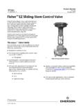
1 Instruction Manual EZ-C, ET-C, and EWT-C valves D102175X012 July 2017. Fisher EZ C, ET C, and EWT C Cryogenic Sliding Stem Control valves Contents Figure 1. Typical Fisher Cryogenic Valve with Introduction .. 1 Extension Bonnet and 585C Series Actuator Scope of Manual .. 1. Description .. 1. Specifications .. 2. Educational Services .. 3. Installation .. 3. Maintenance .. 5. Packing Maintenance .. 7. Replacing Packing .. 7. Trim Maintenance .. 10. EZ C Trim Disassembly .. 10. EZ C Trim Assembly .. 11. ET C and EWT C Trim Disassembly .. 12. ET C and EWT C Valve Plug Maintenance .. 13. ET C and EWT C Trim Assembly .. 14. Coining Soft Metal to Metal Seats .. 14. Parts Ordering .. 14. Parts Kits .. 15. Parts List .. 18. Bonnet Parts .. 18. EZ C Valve Body Parts .. 18 W6370.
2 ET C and EWT C Valve Body Parts .. 22. Introduction Scope of Manual This instruction manual includes installation, maintenance, and parts information for Fisher EZ C, ET C and EWT C. valves (see figure 1). Refer to separate manuals for instructions covering the actuator and accessories. Do not install, operate, or maintain EZ C, ET C or EWT C valves without being fully trained and qualified in valve, actuator, and accessory installation, operation, and maintenance. To avoid personal injury or property damage, it is important to carefully read, understand, and follow all the contents of this manual, including all safety cautions and warnings. If you have any questions about these instructions, contact your Emerson sales office or Local Business Partner before proceeding.
3 Description EZ C: globe style, single port, unbalanced valves with integral end connections, post guiding, metal to metal seating, and quick change trim. They feature stainless steel construction materials and fabricated extension bonnets. ET C and EWT C: metal to metal seated globe style, single port, cage guided, pressure balanced valves featuring stainless steel construction materials and fabricated extension bonnets. EZ-C, ET-C, and EWT-C valves Instruction Manual July 2017 D102175X012. Table 1. Specifications Valve Sizes Material Temperature Capability(2). EZ C: NPS J 1, J 1-1/2, J 2, J 3, and J 4 EZ C: -198 to 149_C (-325 to 300_F). ET C: NPS J 3, J 4, J 6, and J 8. ET C and EWT C: EWT C: NPS J 6X4(1), J 8X4, J 8X6, J 12X6, and -198 to 66_C (-325 to 150_F).
4 J 10X8. Maximum Allowable Actuator Thrust End Connection Styles(2). See table 2. CL150, 300, and 600 raised face flanges per ASME. Flow Characteristics Maximum Inlet Pressure(2) EZ C: Equal percentage, linear, and quick opening CL150 and 300 valves are consistent with ET C and EWT C: Equal percentage and linear pressure temperature ratings per ASME CL600 valves with B8M Class 2 bolting are Flow Directions consistent with CL600 pressure temperature ratings per ASME except as shown below: EZ C:Up through the seat ring only ET C and EWT C: Normally down(4). EZ C valves . Maximum Inlet Pressure Valve Size, NPS. Bar Psig Approximate Weights 1 77 1110 EZ C: 2 83 1200. 3 94 1370 NPS 1: 11 kg (33 lb). NPS 1-1/2: 23 kg (48 lb). ET C AND EWT C valves . NPS 2: 41 kg (90 lb). Maximum Inlet Pressure Valve Size, NPS.
5 Bar Psig NPS 3: 60 kg (130 lb). 3 94 1370 NPS 4: 95 kg (210 lb). 6, 8 x 6, 12 x 6 75 1085. 8, 10 x 8 96 1390 ET C: NPS 3: 51 kg (135 lb). CL600 valves with optional S20910 (XM 19) bolting NPS 4: 95 kg (210 lb). are consistent with CL600 pressure temperature ratings per ASME NPS 6: 211 kg (465 lb). NPS 8: 372 kg (820 lb). Shutoff Classifications per ANSI/FCI 70 2 EWT C. and IEC 60534 4. NPS 6X4: 200 kg (440 lb). VALVE SHUTOFF CLASS. NPS 8X4: 277 kg (610 lb). Class IV Standard EZ C. Class VI Optional NPS 8X6: 318 kg (700 lb). Class IV Standard NPS 12X6: 730 kg (1610 lb). ET C and EWT C Class V Air Test(3). Optional NPS 10X8: 753 kg (1660 lb). 1. Valve size number is end connection size by normal trim size. For example, an NPS 6X4 valve has NPS 6 end connections with NPS 4 trim.
6 2. Do not exceed the pressure/temperature limits in this manual and any applicable code limitation. 3. Class V Air Test is optional. Test will be 50 psid air. Class V shutoff cannot be performed with water. The residual trapped moisture from testing with water can cause valve and trim damage from ice crystals formed at below freezing service temperatures. 4. Down is in through the cage and out the seal ring. (see figure 9). 2. Instruction Manual EZ-C, ET-C, and EWT-C valves D102175X012 July 2017. Table 2. Maximum Allowable Actuator Thrust for Standard Style 3 Bonnet Extension Length MAXIMUM ALLOWABLE STEM LOAD. STEM DIAMETER. VALVE SIZE, NPS FOR S20910 (XM 19) STEM MATERIAL. mm Inches N Lb 3/8 5382 1210. 1. 1/2 13166 2960. 3/8 5338 1200. 1-1/2. 1/2 13166 2960. 1/2 14367 3230.
7 2. 3/4 44169 9930. 1/2 15301 3440. 3. 3/4 45459 10220. 1/2 16458 3700. 4, 6X4, 8X4. 3/4 46971 10560. 3/4 36385 8180. 6, 8X6, 12X6. 1 81487 18320. 3/4 41366 9300. 8, 10X8. 1 87003 19560. Educational Services For information on available courses for Fisher EZ-C, ET-C, and EWT-C valves , as well as a variety of other products, contact: Emerson Automation Solutions Educational Services - Registration Phone: 1-641-754-3771 or 1-800-338-8158. E-mail: Installation Isolate the control valve from the line pressure, release pressure from both sides of the valve body, and drain the process media from both sides of the valve. Remove actuator supply pressure, and use lockout procedures to be sure that the above measures stay in effect while you work on the equipment. Refer to the Warnings at the beginning of the Maintenance section for additional information.
8 WARNING. Always wear protective gloves, clothing, and eyewear when performing any installation operations to avoid personal injury. Personal injury or equipment damage caused by sudden release of pressure may result if the valve assembly is installed where service conditions could exceed the limits given in table 1 or on the appropriate nameplates. To avoid such injury or damage, provide a relief valve for over pressure protection as required by government or accepted industry codes and good engineering practices. Check with your process or safety engineer for any additional measures that must be taken to protect against process media. If installing into an existing application, also refer to the WARNING at the beginning of the Maintenance section in this instruction manual.
9 3. EZ-C, ET-C, and EWT-C valves Instruction Manual July 2017 D102175X012. CAUTION. When ordered, the valve configuration and construction materials were selected to meet particular pressure, temperature, pressure drop, and controlled fluid conditions. Since some valve body/trim material combinations are limited in their pressure drop and temperature ranges, do not apply any other conditions to the valve without first contacting your Emerson sales office or Local Business Partner. Before installing the valve, inspect the valve and pipelines for any damage and any foreign material which may cause product damage. 1. Before installing the valve, inspect the valve and associated equipment for any damage and any foreign material. 2. Make certain the valve body interior is clean, that pipelines are free of foreign material, and that the valve is oriented so that pipeline flow is in the same direction as the arrow on the side of the valve.
10 3. Gas Service: The normal method of mounting for gas service is with the actuator vertical above the valve body. However, the control valve assembly may be installed in any orientation unless limited by seismic criteria. Other positions may result in uneven valve plug and cage wear that could result in improper operation. For mounting assistance, consult your Emerson sales office or Local Business Partner. CAUTION. To avoid possible damage to the packing, do not allow the installed actuator angle to be so flat as to allow liquid inside the bonnet to come in contact with the packing. Also, if insulation is applied, do not let the insulation run up the extension bonnet. This could cause the packing to freeze and be damaged. Liquid Service: The preferred method of mounting for liquid service is with the actuator vertical above the valve body.