Transcription of Fisher FIELDVUE DLC3010 Digital Level Controller - Emerson
1 FIELDVUE DLC3010 Digital LevelControllerThis manual applies to:Device TypeDevice RevisionHardware RevisionFirmware RevisionDD RevisionDLC30101184 ContentsSection 1 Introduction and of Used in this 2 : On the Bench or in the the Coupling and Area Classifications and Special Instructions for Safe Use and Installationsin Hazardous the 249 Level Controller the Digital Level Controller on a 249 the Digital Level Controller for HighTemperature Loop Wire RTD Wire RTD Jumper in Conjunction with a Rosemount 333 HART Tri Loopt HART to AnalogSignal 3 4 Setup and ManualD102748X012 DLC3010 Digital Level ControllerMay 2018 Instruction ManualD102748X012 DLC3010 Digital Level ControllerMay Min/Max Two Point Weight Capture Trim Trim Trim Instrument Trim Process Output Scaled D/A with Standard displacer andTorque with Overweight Applications - with Standard
2 Displacerand Torque at Process Conditions (Hot Cut Over)when input cannot be Theoretical Torque Tube Mechanical the SG of an Unknown of Proportional Variations in Interface 5 Service 6 Maintenance and the Digital LevelController from the the DLC3010 Digital Level Controllerfrom a 249 Temperature Temperature Meter the LCD Meter the LCD Meter the Electronics the Electronics the Terminal the Terminal and Replacing the Inner Guideand Access Handle the Lever the Lever for 7 Digital Level Box Box Cover Sensors with Heat A Principle of Level Controller B Field Communicator Menu ManualD102748X012 DLC3010 Digital Level ControllerIntroduction and SpecificationsMay 20183 Section 1 Introduction and SpecificationsScope of Manual1
3 1 This instruction manual includes specifications, installation, operating, and maintenance information for FIELDVUEDLC3010 Digital Level instruction manual supports the 475 Field Communicator or the AMS Trex Device Communicator with devicedescription revision 4, used with DLC3010 instruments with firmware revision 8. You can obtain information about theprocess, instrument, or sensor using the Field Communicator. Contact your Emerson sales office or Local BusinessPartner to obtain the appropriate Suite: Intelligent Device Manager can also be used to calibrate and configure the DLC3010 , and to obtain information aboutthe process, instrument, or not install, operate, or maintain a DLC3010 Digital Level Controller without being fully trained and qualified ininstrument, valve, actuator, and accessory installation, operation, and maintenance.
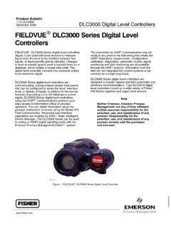
4 To avoid personal injury orproperty damage, it is important to carefully read, understand, and follow all of the contents of this manual, includingall safety cautions and warnings. If you have any questions about these instructions, contact your Emerson sales officeor Local Business Used in this ManualThis manual describes using the Field Communicator to calibrate and configure the Digital Level that require the use of the Field Communicator have the text path and the sequence of numeric keysrequired to display the desired Field Communicator example, to access the Full Calibration menu:Field CommunicatorConfigure > Calibration > Primary > Full Calibration (2-4-1-2)Menu selections are shown in italics, , Calibrate. An overview of the Field Communicator menu structure is shownin Appendix Digital Level ControllersDLC3010 Digital Level controllers (figure 1 1) are used with Level sensors to measure liquid Level , the Level of interfacebetween two liquids, or liquid specific gravity (density).
5 Changes in Level or specific gravity exert a buoyant force on aInstruction ManualD102748X012 DLC3010 Digital Level ControllerIntroduction and SpecificationsMay 20184displacer, which rotates the torque tube shaft. This rotary motion is applied to the Digital Level Controller , transformedto an electrical signal and digitized. The Digital signal is compensated and processed per user configurationrequirements, and converted back to a 4 20 mA analog electrical signal. The resulting current output signal is sent toan indicating or final control 1 1. FIELDVUE DLC3010 Digital Level ControllerW7977-2 DLC3010 Digital Level controllers are communicating, microprocessor based Level , interface, or density sensinginstruments. In addition to the normal function of providing a 4 20 milliampere current signal, DLC3010 Digital levelcontrollers, using the HARTR communications protocol, give easy access to information critical to process can gain information from the process, the instrument, or the sensor using a Field Communicator with devicedescriptions (DDs) compatible with DLC3010 Digital Level controllers.
6 The Field Communicator may be connected atthe Digital Level Controller or at a field junction the Field Communicator, you can perform several operations with the DLC3010 Digital Level Controller . You caninterrogate, configure, calibrate, or test the Digital Level Controller . Using the HART protocol, information from thefield can be integrated into control systems or be received on a single loop Digital Level controllers are designed to directly replace standard pneumatic and electro pneumatic leveltransmitters. DLC3010 Digital Level controllers mount on a wide variety of caged and cageless 249 Level sensors. Theymount on other manufacturers' displacer type Level sensors through the use of mounting Caged Sensors (see table 1 6)D 249, 249B, 249BF, 249C, 249K, and 249L sensors side mount on the vessel with the displacer mounted inside a cageoutside the vessel.
7 (The 249BF caged sensor is available only in Europe, Middle East, and Africa.)249 Cageless Sensors (see table 1 7)D 249BP, 249CP, and 249P sensors top mount on the vessel with the displacer hanging down into the 249VS sensor side mounts on the vessel with the displacer hanging out into the 249W wafer style sensor mounts on top of a vessel or on a customer supplied for the DLC3010 Digital Level Controller are shown in table 1 1. Specifications for the 249 sensor areshown in table 1 3. Specifications for the Field Communicator can be found in the product manual for the ManualD102748X012 DLC3010 Digital Level ControllerIntroduction and SpecificationsMay 20185 Related Documents Other documents containing information related to the DLC3010 Digital Level Controller and 249 sensors include:D Bulletin.
8 DLC3010 - FIELDVUE DLC3010 Digital Level Controller (D102727X012)D FIELDVUE DLC3010 Digital Level Controller Quick Start Guide (D103214X012)D Using FIELDVUE Instruments with the Smart HART Loop Interface and Monitor (HIM) (D103263X012)D Audio Monitor for HART Communications (D103265X012)D Fisher 249 Caged Displacer Sensors Instruction Manual (D200099X012)D Fisher 249 Cageless Displacer Sensors Instruction Manual (D200100X012)D Fisher 249VS Cageless Displacer Sensor Instruction Manual (D103288X012)D Fisher 249W Cageless Wafer Style Level Sensor Instruction Manual (D102803X012)D Simulation of Process Conditions for Calibration of Fisher Level Controllers and Transmitters (D103066X012)D Bolt Torque Information (D103220X012)D Technical Monograph 7: The Dynamics of Level and Pressure ControlD Technical Monograph 18: Level Trol Density TransmitterD Technical Monograph 26: Guidelines for Selection of Liquid Level Control Equipment ()These documents are available from your Emerson sales office or Local Business Partner.
9 Also visit our website Services For information on available courses for the DLC3010 Digital Level Controller , as well as a variety of other products,contact: Emerson Automation SolutionsEducational Services, RegistrationPhone: +1-641-754-3771 or +1-800-338-8158e mail: ManualD102748X012 DLC3010 Digital Level ControllerIntroduction and SpecificationsMay 20186 Table 1 1. DLC3010 Digital Level Controller SpecificationsAvailable ConfigurationsDLC3010 Digital Level Controller :Mounts on caged and cageless 249 sensors. Seetables 1 6 and 1 7 and sensor : TransmitterCommunications Protocol: HARTI nput SignalLevel, Interface, or Density: Rotary motion of torquetube shaft proportional to changes in liquid Level ,interface Level , or density that change the buoyancyof a Temperature: Interface for 2 or 3 wire 100ohm platinum RTD for sensing process temperature,or optional user entered target temperature topermit compensating for changes in specific gravityOutput SignalAnalog: 4 20 milliamperes DC (J directaction increasing Level , interface, or densityincreases output.)
10 Or J reverse action increasinglevel, interface, or density decreases output)High saturation: mALow saturation: mAHigh alarm: mALow Alarm: mAOnly one of the above high/low alarm definitions isavailable in a given configuration. NAMUR NE 43compliant when high alarm Level is : HART 1200 Baud FSK (frequency shift keyed)HART impedance requirements must be met toenable communication. Total shunt impedanceacross the master device connections (excluding themaster and transmitter impedance) must be between230 and 600 ohms. The transmitter HART receiveimpedance is defined as:Rx: 42K ohms and Cx: 14 nFNote that in point to point configuration, analog anddigital signalling are available. The instrument may bequeried digitally for information, or placed in Burstmode to regularly transmit unsolicited processinformation digitally.