Transcription of Fisher FIELDVUE DVC6000 Digital Valve Controllers
1 Fisherr FIELDVUE DVC6000 Digital ValveControllers Instruction Manual(Supported)Supported products may not be manufactured again in any Emerson Process Management location under anyconditions. Spare parts availability is 7 years of best effort. Technical support is sale documents (such as instruction manuals and quick start guides) are available on the CD and FishWeb. Manyare also available at manuals for supported products may be updated, if required, to support products in the sale documents (such as bulletins) for supported products are included on FishWeb for internal use. They are notincluded on the ProductD102794X012 DVC6000 Digital Valve ControllersOctober 2013 Emerson Process Management Marshalltown, Iowa 50158 USAS orocaba, 18087 BrazilChatham, Kent ME4 4QZ UKDubai, United Arab EmiratesSingapore 128461 contents of this publication are presented for informational purposes only, and while every effort has been made to ensure their accuracy, they are notto be construed as warranties or guarantees, express or implied, regarding the products or services described herein or their use or applicability.
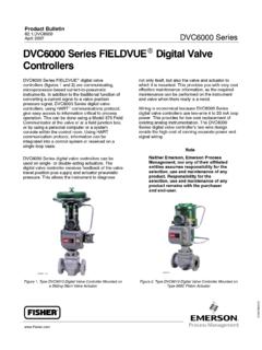
2 All sales aregoverned by our terms and conditions, which are available upon request. We reserve the right to modify or improve the designs or specifications of suchproducts at any time without 2013 Fisher Controls International LLC. All rights and FIELDVUE are marks owned by one of the companies in the Emerson Process Management business unit of Emerson Electric Co. Emerson ProcessManagement, Emerson, and the Emerson logo are trademarks and service marks of Emerson Electric Co. All other marks are the property of their Emerson, Emerson Process Management, nor any of their affiliated entities assumes responsibility for the selection, use or maintenanceof any product. Responsibility for proper selection, use, and maintenance of any product remains solely with the purchaser and end and SpecificationsInstallationBasic SetupDetailed SetupCalibrationViewing Device Variables and DiagnosticsMaintenance and TroubleshootingPartsAppendicesPrinciple of OperationLoop Schematics/NameplatesGlossaryIndexDVC600 0 Digital Valve ControllersInstruction ManualD102794X012 September 2013 Fisherr FIELDVUEt DVC6000 Digital Valve Controllers This manual applies to.
3 Instrument LevelAC, HC, AD, PDHC, AD, PD, ODVACD evice Type030307 Device Revision122 Hardware Revision111 Firmware Revision2 67, 9, 10, 117, 9, 10, 11DD Revision481 Refer to Related Documents on page 1-3 for other documents containinginformation related to DVC6000 Digital Valve Digital Valve ControllersiFast Key Sequence for Instrument Level HC, AD, PD, and ODVF unction/VariableFast-KeySequenceCoordina tes(1)Function/VariableFast-KeySequenceC oordinates(1)A Minus B3-5-34-GEnd Point Pressure Control(3)1-2-2-2-48-DActuator Style1-2-6-43-DFailure Group Enable1-2-3-6-5-111-IAlert Conditions2-12-F1-2-3-7-5-1 Alert Record Full Enable1-2-3-6-210-HFirmware Revision3-7-62-H1-2-3-7-2 Flash ROM Shutdown1-2-3-1-3-512-CAlert Record Has Entries Enable1-2-3-6-110-HHardware Revision3-7-72-H1-2-3-7-1 HART Tag1-2-5-1-16-FAnalog Input3-12-G3-7-12-HAnalog Input Calibration1-3-2-34-EHART Universal Revision3-7-92-HAnalog Input Range Hi1-2-5-3-16-HInput Characterization1-2-2-34-CAnalog Input Range Lo1-2-5-3-26-HInstrument Date and Time1-2-4-1-28-GAnalog Input Units1-2-5-2-36-G1-2-5-84-GAuto Calibration1-3-1-14-EInstrument Level3-7-82-HAutocalibration in Progress Enable1-2-4-2-28-HInstrument ModeHot Key-11-AAuxiliary Input3-6-14-H1-2-1-14-B1-2-3-3-1-212-DIn strument Serial Number1-2-5-1-66-GAuxiliary Terminal Action1-2-3-3-1-312-EInstrument Time Invalid Enable1-2-4-1-18-G1-2-5-74-GIntegral Dead Zone1-2-4-4-48-IAuxiliary Terminal Alert
4 Enable1-2-3-3-1-112-E1-2-2-1-2-18-BBurst Command1-2-1-4-36-BIntegral Enable (Travel Tuning)1-2-2-1-1-28-ABurst Enable1-2-1-4-16-BIntegral Enable (Pressure Tuning)1-2-2-1-3-28-CCalibration in Progress Enable1-2-4-2-18-GIntegral Gain (Travel Tuning)1-2-2-1-1-38-AClear ALL Records1-2-3-6-410-HIntegral Gain (Pressure Tuning)1-2-2-1-3-38-C1-2-3-7-4 Integral Limit1-2-4-4-38-ICommand 3 Configured Pressure1-2-1-4-56 B1-2-2-1-2-28-BControl ModeHot Key-21-AIntegrator Saturated Hi Enable1-2-4-4-18-I1-2-1-24-BIntegrator Saturated Lo Enable1-2-4-4-28-ICritical NVM Shutdown1-2-3-1-3-412-CLast AutoCalibration Status1-2-5-9-16-HCustom Characterization Table1-2-2-44-CLast Calibration Type1-2-5-9-26-HCutoff Hi1-2-3-4-7-312-GLoop Current Validation Enable(6)1-2-3-3-39-E1-2-2-2-2-110-BLow Power Write Fail Enable(6)1-2-3-1-3-212-BCutoff Lo1-2-3-4-7-412-GManual Calibration1-3-1-24-E1-2-2-2-2-210-BManu facturer (Actuator)1-2-6-13-DCycle Counter1-2-3-5-1-212-HManufacturer (Instrument)3-7-32-H3-6-54-HMaximum Recorded Temperature3-6-34-HCycle Counter Alert Enable1-2-3-5-1-112-G2-3-13-FCycle Count Alert Point1-2-3-5-1-312-HMaximum Supply Pressure1-2-5-64-GDate1-2-5-1-46-GMessag e1-2-5-1-26-FDead Band (Cycle Count / TravelAccumulator)1-2-3-5-2-112-HMinimum Recorded Temperature2-3-23-FDescriptor1-2-5-1-36- F3-6-44-HDevice Description Information3-82-GMiscellaneous Group Enable1-2-3-6-5-311-IDevice ID3-7-22-H1-2-3-7-5-3 Device Revision3-7-52-HModel (Device)3-7-42-HDiagnostic Data Available Enable1-2-4-2-48-HMulti-Drop Alert Enable1-2-4-3-28-HDiagnostic in Progress Enable1-2-4-2-38-HNo Free Time Shutdown1-2-3-1-3-612-CDrive Current Shutdown1-2-3-1-18-DNon-Critical NVM Alert Enable1-2-3-1-3-312-CDrive Signal Alert Enable1-2-3-1-2-110-DNumber of Power Ups2-3-43-GDrive Signal3-42-G3-6-94-H1-2-3-1-2-210-DOffli ne/Failed Alert Enable1-2-3-1-3-112-BNOTE.
5 Italicized Fast-Key Sequence indicates fast-key sequence is applicable only for instrument level Coordinates are to help locate the item on the menu tree on the following Instrument level ODV Instrument level HC, AD, and PD Firmware 9 and 10 Digital Valve ControllersiiFast Key Sequence for Instrument Level HC, AD, PD, and ODVF unction/VariableFast-KeySequenceCoordina tes(1)Function/VariableFast-KeySequenceC oordinates(1)Partial Stroke Test(3)2-52-FTravel3-32-GPartial Stroke Test Enable(3)1-2-7-13-D1-2-3-4-19-EPartial Stroke Test Pressure Limit(3)1-2-3-6-110-GTravel / Pressure Select1-2-2-2-16-CPartial Stroke Test Start Point(3)1-2-2-2-4-28-DTravel Accumulatorv3-6-64-HPartial Stroke Test VariablesView/Edit(3)1-2-7-23-D1-2-3-5-3 -212-HPerformance Tuner(2)1-1-22-BTravel Accumulator Alert Enable1-2-3-5-3-112-H1-2-2-1-1-58-ATrave l Accumulator Alert Point1-2-3-5-3-312-IPolling Address1-2-5-1-76-GTravel Alert Dead Band1-2-3-4-39-EPressure A3-5-14-GTravel Alert Hi Enable1-2-3-4-6-110-FPressure B3-5-24-GTravel Alert Hi Hi Enable1-2-3-4-5-112-EPressure Control Active Enable1-2-4-3-18-HTravel Alert Hi Hi Point1-2-3-4-5-312-FPressure Deviation Alert Enable(3)1-2-3-6-210-GTravel Alert Hi Point1-2-3-4-6-310-FPressure Deviation Alert Point(3)1-2-3-6-310-GTravel Alert Lo Enable1-2-3-4-6-210-FPressure Deviation Time(3)1-2-3-6-410-GTravel Alert Lo Lo Enable1-2-3-4-5-212-EPressure Range Hi1-2-2-2-3-110-DTravel Alert Lo Lo Point1-2-3-4-5-412-FPressure Range Lo1-2-2-2-3-210-DTravel Alert Lo Point1-2-3-4-6-410-FPressure Sensor Shutdown(2)
6 1-2-3-2-312-DTravel Deviation Alert Enable1-2-3-4-4-110-EPressure Sensors Calibration1-3-2-14-ETravel Deviation Alert Point1-2-3-4-4-210-EPressure Tuning Set1-2-2-1-3-18-BTravel Deviation Time1-2-3-4-4-310-EPressure Units1-2-5-2-16-GTravel Limit / Cutoff Hi Enable1-2-3-4-7-112-FProtectionHot Key-31-ATravel Limit / Cutoff Lo Enable1-2-3-4-7-212-F1-2-1-54-BTravel Limit Hi1-2-3-4-7-612-GRaw Travel Input3-6-74-H1-2-2-2-2-410-CReference Voltage Shutdown1-2-3-1-3-712-CTravel Limit Lo1-2-3-4-7-712-GRelay Adjust1-3-33-E1-2-2-2-2-510-CRelay Type1-2-5-44-FTravel Sensor Adjust1 3 2 24 ERestart Control Mode1-2-1-34-BTravel Sensor Motion1-2-6-53-ERestore Factory Settings1-3-43-ETravel Sensor Shutdown1-2-3-2-112-CSet Point Rate Close1-2-2-5-25-DTravel Setpoint1-2-3-4-29-ESet Point Rate Open1-2-2-5-15-D3-22-GSetup Wizard1-1-12-BTravel Tuning Set1-2-2-1-1-18-AStabilize/OptimizeHot Key-41-AValve Group Enable1-2-3-6-5-210-H1-1-2(4)2-B1-2-3-7- 5-21-2-2-1-1-48-AValve Serial Number1-2-5-1-56-FStatus2-22-F1-2-6-23-D Stroke Valve2-42-FValve Style1-2-6-33-DSupply Pressure(2)3-5-44-GView Alert Records1-2-3-6-310-H1-2-3-3-2-212-E1-2-3 -7-3 Supply Pressure Lo Alert Enable(5)1-2-3-3-2-112-EView/Edit Feedback Connection1-2-6-63-ESupply Pressure Lo Alert Point(5)1-2-3-3-2-312-EView/Edit Lag Time(5)1-2-2-5-35-DTemperature3-6-24-HVi ew/Edit Lead/Lag(3)1-2-2-5-35-DTemperature Sensor Shutdown1-2-3-2-212-DView Number of Days Powered Up2-3-33-FTemperature Units1-2-5-2-26-G3-6-84-HZero Power Condition1-2-5-54-GNOTE.
7 Italicized Fast-Key Sequence indicates fast-key sequence is applicable only for instrument level Coordinates are to help locate the item on the menu tree on the following Not available in instrument level Instrument level ODV Instrument level HC Instrument level HC, AD, and PD Firmware 7 Digital Valve Controllersiii Hot Key1 Instrument Mode2 Control Mode3 Protection4 Stabilize/OptimizeNotes:1-1-1 indicates fast-key sequence to reach menu1 This menu is available by pressing the leftarrow key from the previous available in instrument level HC3 Instrument level ODV level HC level HC, AD, and PD key sequence for Alert Record with instrument level ODV is menu item reads Power Starvation Alrt Enab in firmware 7 and available in firmware 9, 10, and 11 Field Communicator Menu Tree forInstrument Level HC, AD, PD, and ODV11 2 11-21 2 41 2 1 41 2 51 2 61 31 3 11 3 223 53 61234563522 31 2 71 2 33 7331 2 21 2 5 21 2 5 341 2 2 11 2 2 21 2 2 521 2 5 91 2 5 1 Guided Setup1 Setup Wizard2 Performance Tuner2 Stabilize/OptimizeDetailed Setup1 Mode and Protection2 Response Control3 Alert Setup4 Status5 Instrument6 Valve and Actuator7 SIS/Partial StrokeOnline1 Configure2 Service Tools3 OverviewConfigure1 Guided Setup2 Detailed Setup3 CalibrateHART Application1 Offline2 Online3 Utility4 HART DiagnosticsCalibrate1 Travel Calibration2 Sensor Calibration3 Relay Adjust4 Restore Factory Settings5 PST CalibrationPartial Stroke1 PST Enable2 PST Enable3 PST Vars View/EditBurst Mode1 Burst Enable2 Change Burst Enable3 Burst Command4 Change Burst Command5 Cmd 3 Configured PressureMode and Protection1 Instrument Mode2 Control Mode3 Restart Control Mode4 Burst Mode5 ProtectionDevice Information1 HART Tag2 Device ID3 Manufacturer4 Model5
8 Device Revision6 Firmware Revision7 Hardware Revision8 Instrument Level9 HART Universal RevisionVariables1 Auxiliary Input2 Temperature3 Maximum Recorded Temperature4 Mininum Recorded Temperature5 Cycle Counter6 Travel Accumulator7 Raw Travel Input8 View Number of Days Powered Up9 Number of Power UpsPressure1 Pressure A2 Pressure B3 A Minus B4 SupplyService Tools1 Alert Conditions2 Status3 Device Record4 Stroke Valve5 Partial Stroke TestOverview1 Analog In2 Setpoint3 Travel4 Drive Signal5 Pressure6 Variables7 Device Information8 DD InformationDevice Record1 Maximum RecordedTemperature2 Mininum RecordedTemperature3 View Number of DaysPowered Up4 Number of Power UpsResponse Control1 Tuning2 Travel/Pressure Control3 Input Characterization4 Custom Characterization Table5 Dynamic ResponseTravel Calibration1 Auto Calibration2 Manual CalibrationSensor Calibration1 Pressure Sensors2 Travel Sensor3 Analog InAlert Setup1 Electronics Alerts2 Sensor Alerts3 Environment Alerts4 Travel Alerts5 Travel History Alerts6 SIS Alerts 6 Alert RecordValve & Actuator1 Manufacturer2 Valve Serial Number3 Valve Style4 Actuator Style5 Travel Sensor Motion6 View/ Edit FeedbackConnection7 Assembly Specification SheetTuning1 Travel Tuning2 Integral Settings3 Pressure TuningTravel/Pressure Control1 Travel/Pressure Select2 Cutoffs and Limits3 Pressure Control4 End Point Pressure ControlDynamic Response1 SP Rate Open2 SP Rate Close3 View/Edit Lag Time3 View/Edit Lead/LagInstrument1 General2 Units3 Analog Input Range4 Relay Type5 Zero Power Condition6 Maximum Supply Pressure7 Auxiliary Terminal Action8 Instrument Date and Time9 Calib Status and TypeStatus1 Instrument Time2 Calibration and Diagnostics3 Operational4 Integrator SaturationUnits1 Pressure Units2 Temperature Units3 Analog In UnitsAnalog Input Range1 Input Range Hi2 Input Range
9 LoCalib Status and Type1 Last AutoCal Status2 Last Calibration TypeGeneral1 HART Tag2 Message3 Descriptor4 Date5 Valve Serial Number6 Instrument Serial Number7 Polling Address3633 DVC6000 Digital Valve ControllersivAlert Record1 Alert Record Has Entries Enable2 Alert Record Full Enable3 View Alert Records4 Clear ALL Records5 Alert Groups78 9 10 11 ABCDEFGHI12 Electronics Alerts1 Drive Current Shutdown2 Drive Signal Alert3 Processor Impaired AlertsTravel Tuning1 Travel Tuning Set2 Integral Enable3 Integral Gain4 Stabilize / Optimize5 Performance TunerIntegral Settings1 Integral Dead Zone2 Integral LimitPressure Tuning1 Pressure Tuning Set2 Integral Enable3 Integral GainCutoffs and Limits1 Cutoff Hi2 Cutoff Lo3 Change Cutoffs4 Travel Limit Hi5 Travel Limit Lo6 Change Travel LimitsPressure Control1 Pressure Range Hi2 Pressure Range LoDrive Signal Alert1 Drive Signal Alert Enable2 Drive SignalProcessor Impaired Alerts1 Offline/Failed Alert Enable2 Low Power Write Fail Enable3 Non-Critical NVM Alert Enable4 Critical NVM Shutdown5 Flash ROM Shutdown6 No Free Time Shutdown7 Reference Voltage ShutdownSensor Alerts1 Travel Sensor Shutdown2 Temp Sensor Shutdown3 Pressure Sensor ShutdownEnvironment Alerts1 Auxiliary Terminal Alert2 Supply Pressure Lo Alert3 Loop Current Validation EnableTravel Limit Alerts1 Travel Alert Hi Hi Enable2 Travel Alert Lo Lo Enable3 Travel Alert Hi Hi Point4 Travel Alert Lo Lo PointTravel Alerts1 Travel2 Setpoint3 Travel Alert DB4 Travel Deviation Alert5 Travel Limit Alerts6 Travel Limit Hi/Lo Alerts7 Travel Limit/Cutoff AlertsTravel History Alerts1 Cycle Counter2 Cycle Count/Travel AccumulatorDeadband3 Travel AccumulatorTravel Limit Hi/Lo Alerts1 Travel Alert Hi Enable2 Travel Alert Lo Enable3 Travel Alert Hi Point4 Travel Alert Lo PointTravel Limit/Cutoff Alerts1 Travel Limit/Cutoff Hi Enable2
10 Travel Limit/Cutoff Lo Enable3 Cutoff Hi4 Cutoff Lo5 Change Cutoffs6 Travel Limit Hi7 Travel Limit Lo8 Change Travel LimitsIntegrator Satu