Transcription of Fisher FIELDVUE DVC6200 SIS Digital Valve Controller
1 FIELDVUE DVC6200 SIS Digital ValveControllerThis manual applies toInstrument LevelSISD evice Type130aHardware Revision2 Firmware Revision7 Device Revision1 03DD Revision7 01 ContentsSection 1 , Pneumatic and Electrical Connections, and Initial of Used in this 2 Wiring System Terminal Wiring Length Cable Control 3 and Instrument Point Pressure and Stroke Stroke Test Stroke Abnormal Abort Valve Test Test Terminal Variable to HART 5 / HART ManualD103557X012 DVC6200 SIS Digital Valve ControllerOctober 2018 Instruction ManualD103557X012 DVC6200 SIS Digital Valve ControllerOctober 20182 Contents (continued)Section 4 Input Acting Acting Test 5 Device Information, Alerts & Primary Purpose Principle of Stroke Mode Valve Health 6 Maintenance and the Magnetic Feedback Base the Module the Module Wiring Board (PWB) , Pipe Plugs or Tire the Terminal the Terminal Voltage SIS Technical Support 7 Converter Connection Terminal Gauges, Pipe Plugs, or TireValve Feedback A Principle of SIS Digital Valve B Field Communicator Menu ManualD103557X012 IntroductionOctober 20183 Section 1 Introduction Installation, Pneumatic and Electrical Connections, and Initial ConfigurationRefer to the DVC6200 Series Quick Start Guide (D103556X012)
2 For DVC6200 SISinstallation, connection, and initial configuration information. If a copy of this quick start guide is needed scan or click the QR code at the right, contact your Emersonsales office or visit our website at of ManualThis instruction manual is a supplement to the DVC6200 Series Quick Start Guide (D103556X012) and Safety manual(D103601X012) that ship with every instrument. This instruction manual includes product specifications, referencematerials, custom setup information, maintenance procedures, and replacement part instruction manual describes using the 475 Field Communicator to set up and calibrate the instrument. You canalso use Fisher ValveLink software to setup, calibrate, and diagnose the Valve and instrument. For information on usingValveLink software with the instrument refer to ValveLink software help or not install, operate, or maintain a DVC6200 SIS Digital Valve Controller without being fully trained and qualified invalve, actuator, and accessory installation, operation, and maintenance.
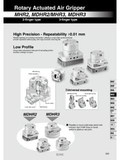
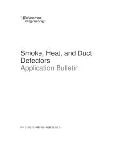
3 To avoid personal injury or property damage,it is important to carefully read, understand, and follow all of the contents of this manual, including all safety cautionsand warnings. If you have any questions about these instructions, contact your Emerson sales office Used in this ManualNavigation paths and fast key sequences are included for procedures and parameters that can be accessed using theField example, to access Device Setup:Field CommunicatorConfigure > Guided Setup > Device Setup (2 1 1)Refer to Appendix B for Field Communicator menu SIS Digital Valve controllers (figure 1 1) are HART communicating, microprocessor basedcurrent to pneumatic instruments. The DVC6200 SIS Digital Valve Controller has three fundamental Modulate a pneumatic output to a Valve actuator in response to a demand signal from a logic solver to move thevalve to a safe Perform periodic tests on a Valve assembly to exercise the mechanical components that are prone to Continuously monitor the health of the Valve and report or click to access field supportInstruction ManualD103557X012 IntroductionOctober 20184 Figure 1 1.
4 FIELDVUE DVC6200 SIS Digital Valve Controller Mounted on a Bettis Quarter-Turn ActuatorX0079 Specifications WARNINGR efer to table 1 1 for specifications. Incorrect configuration of a positioning instrument could result in the malfunction ofthe product, property damage or personal for DVC6200 SIS Digital Valve controllers are shown in table 1 1. Specifications for the FieldCommunicator can be found in the product manual for the Field ManualD103557X012 IntroductionOctober 20185 Table 1 1. SpecificationsAvailable MountingJ Sliding stem linear applicationsJ Quarter turn rotary applicationsJ Integral mounting to Fisher rotary actuatorsJ Integral mounting to Fisher 657/667 or GX actuatorsDVC6200 SIS Digital Valve controllers can also bemounted on other actuators that comply with IEC 60534 6 1, IEC 60534 6 2, VDI/VDE 3845, andNAMUR mounting standardsMounting the instrument vertically, with the vent atthe bottom of the assembly, or horizontally, with thevent pointing down, is recommended to allowdrainage of moisture that may be introduced via theinstrument air supplyCommunication ProtocolJHART 5 or JHART 7 Input SignalPoint-to-PointAnalog Input Signal.
5 4 20 mA DC, nominalMinimum Voltage Available at Instrument Terminalsmust be VDC for analog control, 10 VDC for HART communicationMinimum Control Current: mAMinimum Current w/o Microprocessor Restart: mAMaximum Voltage: 30 VDCO vercurrent protectedReverse Polarity protectedMulti-DropInstrument Power: 11 to 30 VDC at 10 mAReverse Polarity protectedSupply Pressure(1)Minimum Recommended: bar (5 psig) higherthan maximum actuator requirementsMaximum: bar (145 psig) or maximum pressurerating of the actuator, whichever is lowerMedium: Air or Natural GasSupply medium must be clean, dry and noncorrosivePer ISA Standard maximum 40 micrometer particle size in the airsystem is acceptable. Further filtration down to 5micrometer particle size is recommended. Lubricantcontent is not to exceed 1 ppm weight (w/w) orvolume (v/v) basis.
6 Condensation in the air supplyshould be minimizedPer ISO 8573-1 Maximum particle density size: Class 7 Oil content: Class 3 Pressure Dew Point: Class 3 or at least 10_C less thanthe lowest ambient temperature expectedOutput SignalPneumatic Output: up to full supply pressure Minimum Span: bar (6 psig) Maximum Span: bar (140 psig) Action: Double, Single Direct, or Single ReverseElectronic Output(2)J Integral 4 20 mA Position Transmitter:4 20 mA output, isolated Supply Voltage: 8 30 VDCR eference Accuracy: 1% of travel spanSafety Accuracy: 5% of travel spanThe position transmitter meets the requirements ofNAMUR NE43; selectable to show failure high ( > mA) or failure low (< mA). Fail high onlywhen the positioner is Integral Switch: One isolated switch, configurable throughout thecalibrated travel range or actuated from a devicealertOff State: 0 mA (nominal)On State: up to 1 ASupply Voltage: 30 VDC maximumReference Accuracy: 2% of travel spanSafety Accuracy: 5% of travel spanSteady State Air Consumption(3)(4)Low Bleed Relay(5)At bar (20 psig) supply normal m3/hr ( scfh), averageAt bar (80 psig) supply normal m3/hr ( scfh), averageMaximum Output Capacity(3)(4)At bar (20 psig) supply normal m3/hr (375 scfh)At bar (80 psig) supply pressure: normal m3/hr (1100 scfh) continued Instruction ManualD103557X012 IntroductionOctober 20186 Table 1 1.
7 Specifications (continued)Operating Ambient Temperature Limits(1)(6)-52 to 85_C (-62 to 185_F)Independent Linearity(7)Typical Value: + of output spanElectromagnetic CompatibilityMeets EN 61326 1:2013 Immunity Industrial locations per Table 2 of the EN 61326 1 standard. Performance is shown in table 1 2 below. Emissions-Class A ISM equipment rating: Group 1, Class AVibration Testing MethodTested per ANSI/ISA Section Load ImpedanceAn equivalent impedance of 500 ohms may be value corresponds to 10V @ 20 Testing MethodTested per IEC 61514 2 Electrical ClassificationHazardous Area ApprovalsCSA Intrinsically Safe, Explosion-proof, Division 2,Dust Ignition-proofFM Intrinsically Safe, Explosion-proof, DustIgnition-proof, Non-IncendiveATEX Intrinsically Safe, Flameproof, Type n,Dust by intrinsic safetyIECEx Intrinsically Safe, Flameproof, Type n,Dust by intrinsic safety and enclosureAuxiliary Terminal Contact: Nominal ElectricalRating 5 V, <1 mA.
8 It is recommended that theswitch be sealed or have gold plated contacts toavoid corrosionElectrical HousingCSA Type 4X, IP66FM Type 4X, IP66 ATEX IP66 IECEx IP66 Other Classifications/CertificationsLloyds Register Marine Type ApprovalCUTR Customs Union Technical Regulations(Russia, Kazakhstan, Belarus, and Armenia)INMETRO National Institute of Metrology, Quality,and Technology (Brazil)KGS Korea Gas Safety Corporation (South Korea)NEPSI National Supervision and Inspection Centrefor Explosion Protection and Safety ofInstrumentation (China)PESO CCOE Petroleum and Explosives SafetyOrganisation - Chief Controller of Explosives (India)Contact your Emerson sales office forclassification/certification specific informationIEC 61010 Compliance RequirementsPower Source: The loop current must be derived froma separated extra low voltage (SELV) power sourceEnvironmental Conditions: Installation Category IConnectionsSupply Pressure: 1/4 NPT internal and integral pad formounting Fisher 67 CFR regulatorOutput Pressure: 1/4 NPT internalTubing: 3/8 inch recommendedVent: 3/8 NPT internalElectrical: 1/2 NPT internal or M20(8)Actuator CompatibilityStem Travel (Sliding-Stem Linear)Minimum: mm ( inch)Maximum: 606 mm ( inches)Shaft Rotation (Quarter-Turn Rotary)Minimum: 45_Maximum: 90_WeightDVC6200 SISA luminum: kg ( lbs)Stainless Steel: kg (19 lbs)DVC6205 SIS: kg (9 lbs)DVC6215: kg ( lbs) continued Instruction ManualD103557X012 IntroductionOctober 20187 Table 1 1.
9 Specifications (continued)Construction MaterialsHousing, module base, and terminal boxStandard: A03600 low copper aluminum alloy Optional: Stainless steelCover: Thermoplastic polyesterElastomers: FluorosiliconeOptionsJ Supply and output pressure gauges or tire valvesJ Integral mounted filter regulator J Energize to trip J Standard Bleed Relay J Remote mount(9)(10) J LCP100 local control panel J Fisher LC340 lineconditioner J Stainless steelDeclaration of SEPF isher Controls International LLC declares thisproduct to be in compliance with Article 4 paragraph3 of the PED Directive 2014/68/EU. It was designedand manufactured in accordance with SoundEngineering Practice (SEP) and cannot bear the CEmarking related to PED , the product may bear the CE marking toindicate compliance with other applicable EuropeanCommunity : Specialized instrument terms are defined in ANSI/ISA Standard Process Instrument The pressure/temperature limits in this document and any other applicable code or standard should not be The electronic output is available with either the position transmitter or the Normal m3/hour Normal cubic meters per hour at 0_C and bar, absolute.
10 Scfh Standard cubic feet per hour at 60_F and Values at bar (20 psig) based on single acting direct relay; values at bar (80 psig) based on double acting The Quad O steady-state consumption requirement of 6 scfh can be met by a DVC6200 SIS with low bleed relay when used with up to bar (53 psi) supply of Natural Gas at 16_C (60_F).6. Temperature limits vary based on hazardous area approval. Lower temperature limit for CUTR Ex d approval with fluorosilicone elastomers is -53_C ( ).7. Not applicable for travels less than 19 mm ( inch) or for shaft rotation less than 60 degrees. Also not applicable for Digital Valve controllers in long-stroke applications over M20 electrical connections are only available with ATEX 4 conductor shielded cable, 18 to 22 AWG minimum wire size, in rigid or flexible metal conduit, is required for connection between base unit and feedback unit.