Transcription of Floating Joint - content2.smcetech.com
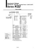
1 RoHSSeriesCylinder supply pressureApplicable bore size (mm)MountingPage1144 Standard JA SeriesBasic typeFlange typeFoot type1151 Heavy load JAH SeriesBasic typeFlange typeFoot type1154 For compact cylindersJB SeriesBasic type(Female thread)Stainless steel typeJS SeriesBasic type1156 hydraulic cylinderPneumatic cylinderHydraulic cylinderPneumatic cylinderPneumatic cylinderHydraulic cylinder6, 10, 1520, 25, 30, 40, 50, 6380, 100, 125, 140, 16020, 25, 30, 40, 50, 6380, 100, 125, 140, 16040, 50, 63, 80, 10012, 16, 20, 25, 3240, 50, 63, 80, 10010, 16, 20, 2532, 40, 50, 6320, 25, 3240, 50, MPa or less1 MPa or MPa or less7 MPa or less1 MPa or less1 MPa or MPa or lessSeries VariationsJA/JAH/JB/JS SeriesFloating JointThe Floating Joint can absorb any off-centering or loss of parallel accuracy between the cylinder and the driven is high level of machining accuracy is installation time is dramatically is compact and is suitable for high tensile service life (with dustproof cover)
2 Rotating angle 5 Operating rangeCenter of sphereOperating rangeAxial centerSpherical rotationEccentric slide1143J D- -X TechnicalDataJ PrecautionsMountingWarningSpecifications Basic type, Flange type, Foot typeMountingOperating rangeJA3-0504-0705-0806-1008-12510-12514 -15018-15022-15026-15030-15036-150M3 x x x x 1M8 x x x x x x x x 40F14-15061010, 152025, 324050, 6380100125, 140160180200 Model/SpecificationsNoneBe sure to read this before handling the products. Refer to back page 50 for Safety cylinder:1 MPa or lessHydraulic cylinder: MPa or lessCenter of sphereAxial centerOperatingrange1. To screw the male threads of the rod into the female threads of the socket or the case, make sure that it does not bottom the Floating Joint is used with its rod bottom out, the stud will not be able to float, causing the screw-in depth of the female threads, refer to the dimensions (page 1146). As a rule, after the rod bottoms out, back off 1 to 2 The dust cover may adhere to the stud.
3 In this case, move the dust cover at the neck of the stud by the finger or twist the stud slightly left or right to break in the dust cover before , when screwing the stud and socket or the case into a driven body, screw in such parts with the dust cover removed. When screwing in such parts without removing the dust cover, this may cause damage to the dust cover. 3. To use a Floating Joint to connect the cylinder rod to a driven body, secure it in place by applying a torque that is appropriate for the thread size. Also, if there is a risk of loosening during operation, take measures to prevent loosening, such as using a locking pin or thread the event that the connected portion becomes loose, the driven body might lose control or fall off, leading to equipment damage or injury to This product is not a rotary Joint . So, the product cannot be used for rotational or rotation acting applications. 5. Be sure to use the cushion mechanism of the cylinder or the buffer mechanism, such as the shock absorber so that any impact force is not applied to the Floating Joint when stopping a driven body.
4 If there is no buffer mechanism, an excessive impact force is generated. As a result, the tensile compression force of the Floating Joint may exceed its maximum to OrderMounting typeNilFLBasic typeFlange typeFoot typeApplicable bore size (mm)SymbolApplicablebore size (mm)ModelStandardThread nominal size(Standard)Nominalthread sizeApplicable cylindernominal thread sizeOptionX11 NilHigh temperaturespecifications 5 to 100 CFloating Joint : Standard TypeJA SeriesRoHSMaintenanceWarning1. Do not reuse if strength adhesive is applied to the portion of the connection that is threaded to prevent it from loosening, and it must not be disassembled. If it is forcefully disassembled, it could lead to seriesMade to Order: Individual Specifications -X530 Note) For details, refer to page 1149. For pneumatic cylinders610152030406380100140160180200 ModelApplicablebore size(mm)Applicablecylindernominalthread sizeRotatingangleAmbienttemperatureAllow ableeccentricityU (mm)Maximum operating tensionand compression force (N)Basic typeFlange typeFoot typeStandard/Thread nominal sizeSemi-standard/Thread nominal sizeJA6-3-050JA10-4-070JA15-5-080JA15-6- 100JA 20-8-125JA 30-10-125JA 40-14-150JA 63-18-150JA 80-22-150JA 100-26-150JA 140-30-150JA 160-36-15061010, 15152025, 324050, 6380100125, 140160M3 x x x x 1M8 x x x x x x x x 1100250044001100018000280003600055000 20-8-100JA 25-10-150JA 32-10-100JA 40-12-125JA 40-12-150JA 40-12-175JA 50-16-150JA 63-16-200JA 80-20-250JA 100-24-300JA 100-27-150JA 125-27-200JA 160-33-20020253232, 404032, 405050, 6380100100125160M8 x 1M10 x x 1M12 x x x x x 2M20 x x 3M27 x x 2M33 x 5 5 -5 to 60 C1.
5 The black zinc chromate treatment is applied to the material surfaces of the case, flange and foot. However, the white deposit may rarely occur on the surface. This white deposit does not affect the product functions. However, if the white deposit becomes a problem from a viewpoint of appear-ance, special products with the surface treatment changed to the electroless nickel plating are also available. For details, please contact 1M8 1M8 1M10 2M18 4 5 5 5 6 6 6 7 7 7 8101011 7 810131317171719191922242427BC 2M24 3M26 2M30 2M33 2M36 3M48 : Threadnominal sized: Threadnominal size(mm)(mm)Part no. for dust coverP2152051P2152052P215215P215225P2152 35P215245 Applicable modelJA6, JA10JA15, JB12, JB16JA20, JB20JA30, JB30JA40, JB40JA63, JA50, JB63 Part no. for dust coverP215255P215265P215275P215285P215295 Applicable modelJA80, JAH40, JB80JA100, JAH50, JB100JA125, JAH63JA140, JAH80, JB140JA160, JAH100, JB160 Component steelBrassStainless steelBrassSynthetic rubber Low carbon steel wire rodNoteElectroless nickel platedElectroless nickel platedElectroless nickel platedZinc chromatedStudCaseRingSocketDust coverRod end molybdenum steelCarbon steelChromium molybdenum steelCarbon steelSynthetic rubber Carbon steelCarbon steelRolled steelRolled steelNoteDyed blackBlack zinc chromatedBlack zinc chromatedZinc chromatedZinc chromatedBlack zinc chromatedBlack zinc chromatedStudCaseRingCap Dust coverSet screwRod end nutFlangeFootEccentric slideSpherical rotationEccentric slideSpherical rotationConstruction 6 to 15 20 to 160 Accessory DimensionsRod end nutFloating Joint Replacement PartsDust coverOrder with the following part no.
6 If dust cover is dust cover is only for the basic type. Flange type and foot type cannot be rod end nut is supplied with the JA series or JAH basic type. If additional nuts are needed, please order them using the part no. shown Joint : Standard Type JA SeriesJ D- -X TechnicalDataJ Applicablebore size(mm)Model610 (CJ1)10 (CZ1), 15 (CJ1)15 (CZ1)2025, 324050, 6380100125, , 404032, 405050, 3035 (mm)Center ofsphereCenter ofsphereNominalsizePitchCenter ofsphereRWeight(kg)Maximum operatingtension andcompressionforce (N)Standard Pneumatic: Up to 1 MPa hydraulic : Up to MPaSemi-standard Pneumatic: Up to 1 MPa hydraulic : Up to MPaBasic Type: JA6 to JA160JA6 to 15JA SeriesJA20 to 160 Without C-dimensionUse the precision spanner for clock 4 mm in the case of mounting male thread of JA6 and depthPAllowableeccentricityU1146R R 2025, 324050, 6380100125, , 404032, 405050, (mm) x x Center of sphereCenter of sphereApplicablebore size(mm)ModelPitchNominalsizeWeight(kg)C enter ofsphereRMaximum operatingtension andcompressionforce (N)Standard Pneumatic: Up to 1 MPa hydraulic : Up to MPaSemi-standard Pneumatic: Up to 1 MPa hydraulic : Up to MPaFloating Joint .
7 Standard Type JA SeriesFlange Type: JAF20 to JAF160 JAF20 to 40 JAF50 to 160 Maximumthread depthPAllowableeccentricityU1147J D- -X TechnicalDataJ 2025, 324050, 6380100125, , 404032, 405050, (mm)Standard Pneumatic: Up to 1 MPa hydraulic : Up to MPaSemi-standard Pneumatic: Up to 1 MPa hydraulic : Up to MPaApplicablebore size(mm)ModelPitchNominalsizeWeight(kg)C enter ofsphereRMaximum operatingtension andcompressionforce (N)Foot Type: JAL20 to JAF160 JAL20 to 100 JAL125 to 160JA SeriesCenter of sphereR 2 x J4 x JCenter of sphere RMaximumthread depthPAllowableeccentricityU1148JA SeriesMade to Order: Individual SpecificationsPlease contact SMC for detailed dimensions, specifications and lead series standard type Floating Joint which is used for pneumatic cylinders ( 180, 200)* This product is dedicated to the pneumatic Pneumatic Cylinders ( 180, 200)-X530 Symbol1 Basic Type: JADimensionsApplicablebore sizeModelMABDEFGHC enter ofsphereRMaximumscrew-indepth PAllowableeccentricityUMaximum operatingtensile andcompressive force(N)Weight(kg) 200- -X530H DGPABEMC enter ofsphereUUWidth acrossflats F60 MR(mm)How to OrderJAF18040-150 Mounting typeNilBasic typeFFlange typeLFoot typeApplicable bore sizeSymbolApplicablebore size180180 mm200200 mmNominal thread sizeNominal thread sizeApplicable cylindernominal thread size40-150M40 x x pneumatic cylinders ( 180, 200)Applicablebore size(mm)ModelApplicablecylindernominal threadsizeMaximum operating tensileand compressive force (N)Allowableeccentricity(U)Rotatingangle AmbienttemperatureBasic typeFlange typeFoot type180JA 180-40-150-X530M40 x 5 to 60 C200JA 200-45-150-X530M45 x pressurePneumatic cylinder.
8 1 MPa or lessMountingBasic type, Flange type, Foot typeOperating rangeAxialcenterCenter ofsphereOperating range5 5 UUX5301149J D- -X TechnicalDataJ M60 UU B CH4 x J DAGPTC enter ofsphereRUU60 MCenter of sphereBETCH4 x J DGPARKLFCBHdFlange Type: JAFFoot Type: JALRod End NutFloating Joint Replacement PartsDimensionsApplicablebore sizeModelMABCDEFKLTJGHC enter ofsphereRMaximumscrew-indepth PAllowableeccentricityUMaximum operatingtensile andcompressive force(N)Weight(kg) 116 55967448 151 116 55967448 151 (mm)ModelOrder : Nominal thread sizeHBCJA180-40-150-X530DA00425M40 x x 200- -X530 Dust coverWhen the dust cover is damaged and deteriorated, order with the part number below. Replaceable dust cover is only for the basic type. Flange type and foot type cannot be no. for dust coverApplicable modelP215295JA180, 200- -X530 The basic type has one rod end nut attached, it is possible to order additional pieces by the order numbers below.(mm)DimensionsApplicablebore sizeModelMABCDTJGHC enter ofsphereRMaximumscrew-indepth PAllowableeccentricityUMaximum operatingtensile andcompressive force(N)Weight(kg) 200- -X530(mm)1150JA SeriesJAH seriesJAHL series(Foot type)JAHF series(Flange type)PrecautionsMountingWarningMaintenan ceWarningSpecificationsSpecificationsSta ndard/ Thread nominal sizeSemi-standard/Thread nominal sizeJAH 40-16-150 JAH 50-20-150 JAH 63-24-150 JAH 80-30-150 JAH 100-39-150 JAH 100-48-15040506380100100 JAH 63-24-200 JAH 80-30-200 JAH 100-42-3006380100M24 x 2M30 x 2M42 x x x x x x x to OrderJA H16-15020-15024-15030-15039-15048-150M16 x x x x x x cylinder.
9 7 MPa or lessBasic type, Flange type, Foot typeMountingOperating rangeCenter of sphereAxial centerOperating rangeModelApplicablebore size(mm) Applicablecylindernominalthread sizeMaximum operating tensionand compression force (N)Basic typeFlange typeFoot typeRotatingangleAmbienttemperatureAllow ableeccentricityU (mm) 5 5 Heavy load typeMounting typeNilFLBasic typeFlange typeFoot typeApplicable bore size (mm)ModelSymbolApplicable bore size(mm)Heavyload typeX11 High temperature specifications 5 to 100 COptionNilNoneThread nominal size(Standard)Nominalthread sizeApplicable cylindernominal thread sizeBe sure to read this before handling the products. Refer to back page 50 for Safety screw the male threads of the rod into the female threads of the socket or the case, make sure that it does not bottom out. If the Floating Joint is used with its rod bottomed out, the stud will not be able to float, causing damage. For the screw-in depth of the female threads, refer to the dimensions (page 1152).
10 As a rule, after the rod bottoms out, back off 1 to 2 The dust cover may adhere to the stud. In this case, move the dust cover at the neck of the stud by the finger or twist the stud slightly left or right to break in the dust cover before , when screwing the stud and socket or the case into a driven body, screw in such parts with the dust cover removed. When screwing in such parts without removing the dust cover, this may cause damage to the dust cover. use a Floating Joint to connect the cylinder rod to a driven body, secure it in place by applying a torque that is appropriate for the thread size. Also, if there is a risk of loosening during operation, take measures to prevent loosening, such as using a locking pin or thread the event that the connected portion becomes loose, the driven body might lose control or fall off, leading to equipment damage or injury to product is not a rotary Joint .