Transcription of Floatless Level Switch (Basic Type) 61F-G
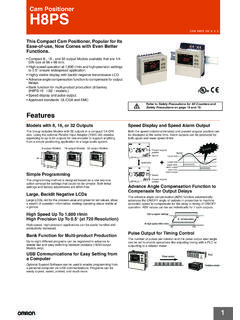
1 Floatless Level Switch ( basic type ). 61F-G @ CSM_61F-G__DS_E_4_3. Basic Building-block Controllers That Mount Directly to Panels for Easier Maintenance Easy maintenance with building-block Relay Units. Easy identification of operating status with LED operation indicator. Lineup includes models for tropical regions and for high temperatures. Achieve stable detection even in high- temperature environments. Refer to Safety Precautions for Floatless Level Controllers. Some specifications for 61F-G @ Series products in this catalog Model Number Structure have been discontinued at the end of March 2018. 61F-@ 1 2. Position of 1. Control Application 2. Type LED indicator G: Automatic water supply and drainage Blank: General-purpose G1: Automatic water supply with idling prevention or water L 2KM: Long-distance (for 2 km). shortage alarm L 4KM: Long-distance (for 4 km). G2: Automatic water supply and drainage with abnormal H: High-sensitivity water increase alarm D: Low-sensitivity G3: Automatic water supply and drainage with full tank and R: Two-wire water shortage alarm T: High-temperature G4: Automatic water supply with water Level indicator for water supply tank and water receiving tank and prevention of idling due to water shortage I: Liquid Level indication and alarm (no two-wire models).
2 1. Ordering Information Type Set contents General-purpose Long-distance, 2 km Long-distance, 4 km High-sensitivity Model Model Model Model Application G 61F-G Base x 1 61F-G * 61F-GL 2KM * 61F-GL 4KM * 61F-GH *. 61F-11@ Units x 1. Application G1 61F-G1 Base x 1 61F-G1 * 61F-G1L 2KM 61F-G1L 4KM 61F-G1H *. 61F-11@ Units x 2. Application G2 61F-G2 Base x 1 61F-G2 * 61F-G2L 2KM * 61F-G2L 4KM * 61F-G2H *. 61F-11@ Units x 2. Application G3 61F-G3 Base x 1 61F-G3 * 61F-G3L 2KM 61F-G3L 4KM 61F-G3H *. 61F-11@ Units x 3. Application G4 61F-G4 Base x 1 61F-G4 * 61F-G4L 2KM 61F-G4L 4KM * 61F-G4H *. 61F-11@ Units x 5. MK3P Relay x 1. Application I 61F-I Base x 1 61F-I * 61F-IL 2KM 61F-IL 4KM 61F-IH. 61F-11@ Units x 2. Relay Unit 61F-11@ Units x 1 61F-11 61F-11L 2KM 61F-11L 4KM 61F-11H. Type Set contents Low-sensitivity 2-wire Tropical environments High-temperature Model Model Model Model Application G 61F-G Base x 1 61F-GD 61F-GR 61F-G -TDL * 61F-GT *. 61F-11@ Units x 1. Application G1 61F-G1 Base x 1 61F-G1D 61F-G1R 61F-G1-TDL * 61F-G1T.
3 61F-11@ Units x 2. Application G2 61F-G2 Base x 1 61F-G2D 61F-G2R 61F-G2-TDL * 61F-G2T *. 61F-11@ Units x 2. Application G3 61F-G3 Base x 1 61F-G3D 61F-G3R 61F-G3-TDL * 61F-G3T. 61F-11@ Units x 3. Application G4 61F-G4 Base x 1 61F-G4D 61F-G4R 61F-G4-TDL * 61F-G4T. 61F-11@ Units x 5. MK3P Relay x 1. Application I 61F-I Base x 1 61F-ID * --- 61F-I-TDL * 61F-IT. 61F-11@ Units x 2. Relay Unit 61F-11@ Units x 1 61F-11D 61F-11R --- 61F-11T. Note: 1. When ordering, specify the desired operating voltage at the end of the model number. Example: 61F-G [110/220 VAC]. Desired supply voltage 2. If you order with a standard model number, the corresponding Relay Units are also delivered as part of a set. If you order the 61F-G , one 61F-11 Relay Unit is included in the set. * Orders will not be accepted after March 31, 2018. Refer to the following table for the discontinued power supply voltages. Discontinued at the end of March 2018. 61F-G G G1 G2 G3 G4 I. Voltage Model Model Model Model Model Model 120/240 V 61F-G 61F-G1 61F-G2 61F-G3 61F-G4 61F-I.
4 120/240 VAC 120/240 VAC 120/240 VAC 120/240 VAC 120/240 VAC 120/240 VAC. 115/230 V 61F-G2 61F-G3 61F-G4 61F-I. 115/230 VAC 115/230 VAC 115/230 VAC 115/230 VAC. 200/220 V 61F-G 61F-I. 200/220 VAC 200/220 VAC. 220/380 V 61F-G 61F-G1 61F-G2 61F-G3 61F-G4 61F-I. 220/380 VAC 220/380 VAC 220/380 VAC 220/380 VAC 220/380 VAC 220/380 VAC. 120/240 V 61F-GL 61F-G2L. 120/240 VAC 2KM 120/240 VAC 2KM. 120/240 V 61F-GL 61F-G2L 61F-G4L. 120/240 VAC 4KM 120/240 VAC 4KM 120/240 VAC 4KM. 120/240 V 61F-GH 61F-G1H 61F-G2H 61F-G3H 61F-G4H. 120/240 VAC 120/240 VAC 120/240 VAC 120/240 VAC 120/240 VAC. 115 V 61F-ID. 115 VAC. 120/240 V 61F-GT. 120/240 VAC. 120/240 V 61F-G2T. 120/240 VAC. 100/200 V 61F-G -TDL 61F-G1-TDL 61F-G2-TDL 61F-G3-TDL 61F-G4-TDL 61F-I-TDL. 100/200 VAC 100/200 VAC 100/200 VAC 100/200 VAC 100/200 VAC 100/200 VAC. 110/220 V 61F-G -TDL 61F-G1-TDL 61F-G2-TDL 61F-G3-TDL 61F-G4-TDL. 110/220 VAC 110/220 VAC 110/220 VAC 110/220 VAC 110/220 VAC. 2. Specifications Standard Models Specifications Items General-purpose High- Long-distance High-sensitivity Low-sensitivity Two-wire Controller temperature Controllers Controllers Controller Controller Controller 61F-@ (TDL) 61F-@L 2KM 61F-@H 61F-@D (see note 61F-@T (for 2 km) (see note 1) (see note 1) (see note 1).)
5 1 and 2) (see note 1) 61F-@L 4KM. (for 4 km). (see note 1). Controlling materials For control of ordi- For control of ordi- For control of ordi- For control of liq- For control of liq- For control of ordi- and operating condi- nary purified water nary purified water nary purified water uids with high uids with low spe- nary purified water tions or sewage water or sewage water in cases where the specific resis- cific resistance or sewage water in cases where the distance between tance such as dis- such as salt water, used in combina- ambient tempera- sewage pumps tilled water sewage water, tion with Two-wire ture is high. and water tanks or acid chemicals, al- Electrode Holder between receiver kali chemicals (incorporating a tanks and supply resistor of k ). tanks is long or It is possible to wire where remote with less than one control is required. wiring against gen- eral 61F's wiring. Supply voltage 100, 110, 120, 200, 220 or 240 VAC; 50/60 Hz Operating voltage range 85% to 110% of rated voltage InterElectrode voltage 8 VAC 24 VAC 8 VAC.
6 InterElectrode current Approx. 1 mA AC max. Power consumption 61F-G @: VA max.; G1F-G1@, G1F-G2@, or G1F-I@: VA max.; G1F-G3@: VA max.; G1F-G4@: VA max. InterElectrode operate 0 to approx. 4 k 0 to approx. 5 k 0 to approx. Approx. 15 k to 0 to approx. 0 to approx. k . resistance k (for 2 km) 70 k k . 0 to approx. (see note 5). k (for 4 km). InterElectrode release Approx. 15 k to Approx. 15 k to 4 k to (for Approx. 300 k to Approx. 5 k to Approx. 15 k to resistance 2 km) . k to (for 4 km). cable length 1 km max. 600 m max. 2 km max. 50 m max. 1 km max. 800 m max. (see note 3) 4 km max. Control output 2 A, 220 VAC (Inductive load: cos = ). 5 A, 220 VAC (Resistive load). Ambient temperature Operating: 10 to 55 C ( 10 to 70 C for Ambient humidity Operating: 45% to 85% RH. Insulation resistance 100 M min. (at 500 VDC). (see note 4). Dielectric strength 2000 VAC, 50/60 Hz for 1 min. (see note 4). Life expectancy Electrical: 500,000 operations min. Mechanical: 5,000,000 operations min.)
7 Weight 61F-G @: Approx. 380 g, G1F-G1@, G1F-G2@, or G1F-I@: Approx. 750 g; G1F-G3@: Approx. 930 g;. G1F-G4@: Approx. 1,710 g Note: 1. The @ in the model name represents G, G1, G2, G3, G4, and I. 2. The suffix TDL attached to the model name represents models designed for tropical regions (storage humidity of 45% to 90%). For details, refer to Safety Precautions for Floatless Level Controllers. 3. The length when using completely- insulated , 600-V, 3-conductor ( mm2) cabtire cables. Usable cable lengths will become shorter as the cable diameter or number of conductors becomes larger. For details, refer to Safety Precautions for Floatless Level Controllers. 4. The insulation resistance and dielectric strength indicate values between power terminals and Electrode terminals, between power ter- minals and contact terminals, and between Electrode terminals and contact terminals. 5. Possible to use with 15 k or less, however, this may cause reset failure. 6. High-sensitivity Controllers use advanced operation.
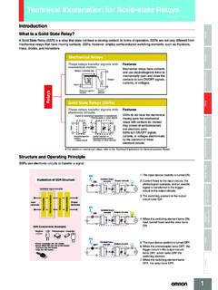
8 When the power supply voltage is applied, if there are some liquids between the electrodes (ground and operation electrodes), the inter- nal relay will not operate. When the power supply voltage is applied, if there are no liquids between the electrodes (ground and operation electrodes), the internal relay will operate. Advanced Operation With advanced operation, the internal relay operates as soon as control power is supplied to the G1F and is reset when current flows between the poles. Wiring is the same as for models with sequential operation. 3. Internal Circuit Diagrams The schematic diagrams shown below typify the internal connections of the various 61F models. The designations Ta, Tb, and Tc (sometimes referred to collectively as U ) may occur more than once in a product, however, the a terminal is always an NO contact, a b terminal is an NC. contact, and the c terminal is the common terminal. 61F-G 61F-GT 61F-GL. 0V 0V 0V. 61F-11 61F-11T U 100, 110 61F-11L U.
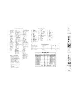
9 100, 110 24 V U 100, 110 24 V 24 V Relay Unit or 120 V Relay Unit or 120 V Relay Unit or 120 V. 200, 220 200, 220 200, 220. 8V 8V or 240 V 8V. or 240 V or 240 V. U U U. U U U. Ta Tc Tb E2 E1 Ta Tc Tb E2 E1 Ta Tc Tb E2 E1. S0 S1 S2 E3 S0 S1 S2 E3 S0 S1 S2 E3. 61F-GH 61F-GD 61F-GR. (See note.) 0V. 0V. 100, 110 61F-11R U. 0V 100, 110 61F-11D U 24 V Relay Unit 100, 110 61F-11H U 24 V Relay Unit or 120 V. 24 V Relay Unit or 120 V 200, 220. or 120 V 200, 220 8V. 200, 220 8V or 240 V. or 240 V. or 240 V 24 V. U. U. U. U. U. U. Ta Tc Tb E1. Ta Tc Tb E2 E1. Ta Tc Tb E2 E1. S0 S1 S2 E3. S0 S1 S2 E3. S0 S1 S2 E3. 4. Note: The 61F11H relay deenergizes when there is water present across the Electrodes, whereas the 61F relay energizes when there is water present across the Electrodes. Also, the terminal connections of those Controllers provided with LED indicators differ from those which have no indicators. 61F-11 Relay Units Item 61F-11 61F-11T 61F-11L 61F-11H 61F-11D 61F-11R. Interchangeable with --- Provided Provided Not provided Provided Not provided general-purpose mod- el (61F-11).
10 Color of band on name --- Red Yellow Blue Black Green plate 61F-11 61F-11T 61F-11L. E S S S E S S S E S S S. 8 7 6 5 4 8 7 6 5 4 8 7 6 5 4. 8V 24 V 24 V 8V 24 V 24 V 8V 24 V 24 V. Tr2 Tr2 Tr1 Tr2. Tr1 X Tr1 X X. x x x x x x 9 10 11 1 2 3 9 10 11 1 2 3 9 10 11 1 2 3. Tb2 Ta2 Tc2 Tc1 Ta1 Tb1 Tb2 Ta2 Tc2 Tc1 Ta1 Tb1 Tb2 Ta2 Tc2 Tc1 Ta1 Tb1. 61F-11H Tr2 61F-11D 61F-11R. (see note). E S S S E S S S E S S S. 8 7 6 5 4 8 7 6 5 4 8 7 6 5 4. 24 V 24 V 24 V 8V 24 V 24 V 8V 24 V 24 V. Tr2 Tr2 Tr1 Tr2. Tr1 X Tr1 X X. x x x x x x 9 10 11 1 2 3 9 10 11 1 2 3 9 10 11 1 2 3. Ta2 Tb2 Tc2 Tc1 Tb1 Ta1 Tb2 Ta2 Tc2 Tc1 Ta1 Tb1 Tb2 Ta2 Tc2 Tc1 Ta1 Tb1. 5. Connections Automatic Water Supply and basic type Drainage Control 61F-G . Dimensions: page 14. Automatic Water Supply Control Automatic Drainage Control Connections Connections 61F-G 61F-G . 220-VAC power supply 220-VAC Power supply R S T 0V R S T 0V. 24 V 61F-11 U 24 V 61F-11 U. 110 V Relay Unit 110 V Relay Unit MCCB 8V U MCCB 8V U. 220 V 220 V.