Transcription of FLUID MECHANICS 203 TUTORIAL No.2 APPLICATIONS OF …
1 1 FLUID MECHANICS 203 TUTORIAL APPLICATIONS OF BERNOULLI On completion of this TUTORIAL you should be able to derive Bernoulli's equation for liquids. find the pressure losses in piped systems due to FLUID friction. find the minor frictional losses in piped systems. match pumps of known characteristics to a given system. derive the basic relationship between pressure, velocity and solve problems involving flow through orifices. solve problems involving flow through Venturi meters. understand orifice meters. understand nozzle meters. understand the principles of jet pumps solve problems from past papers. Let's start by revising basics. The flow of a FLUID in a pipe depends upon two fundamental laws, the conservation of mass and energy. 2 1.
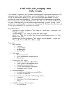
2 PIPE FLOW The solution of pipe flow problems requires the APPLICATIONS of two principles, the law of conservation of mass (continuity equation) and the law of conservation of energy (Bernoulli s equation) CONSERVATION OF MASS When a FLUID flows at a constant rate in a pipe or duct, the mass flow rate must be the same at all points along the length. Consider a liquid being pumped into a tank as shown ( ). The mass flow rate at any section is m = Aum = density (kg/m3) um = mean velocity (m/s) A = Cross Sectional Area (m2) For the system shown the mass flow rate at (1), (2) and (3) must be the same so 1A1u1 = 2A2u2 = 3A3u3 In the case of liquids the density is equal and cancels so A1u1 = A2u2 = A3u3 = Q 3 CONSERVATION OF ENERGY ENERGY FORMS FLOW ENERGY This is the energy a FLUID possesses by virtue of its pressure.
3 The formula is = pQ Joules p is the pressure (Pascals) Q is volume rate (m3) POTENTIAL OR GRAVITATIONAL ENERGY This is the energy a FLUID possesses by virtue of its altitude relative to a datum level. The formula is = mgz Joules m is mass (kg) z is altitude (m) KINETIC ENERGY This is the energy a FLUID possesses by virtue of its velocity. The formula is = mum2 Joules um is mean velocity (m/s) INTERNAL ENERGY This is the energy a FLUID possesses by virtue of its temperature. It is usually expressed relative to 0oC. The formula is U = mc c is the specific heat capacity (J/kg oC) is the temperature in oC In the following work, internal energy is not considered in the energy balance. SPECIFIC ENERGY Specific energy is the energy per kg so the three energy forms as specific energy are as follows.
4 = pQ/m = p/ Joules/kg = gz Joules/kg = u2 Joules/kg ENERGY HEAD If the energy terms are divided by the weight mg, the result is energy per Newton. Examining the units closely we have J/N = N m/N = metres. It is normal to refer to the energy in this form as the energy head. The three energy terms expressed this way are as follows. = p/ g = h = z = u2 /2g The flow energy term is called the pressure head and this follows since earlier it was shown that p/ g = h. This is the height that the liquid would rise to in a vertical pipe connected to the system.
5 The potential energy term is the actual altitude relative to a datum. The term u2/2g is called the kinetic head and this is the pressure head that would result if the velocity is converted into pressure. 4 BERNOULLI S EQUATION Bernoulli s equation is based on the conservation of energy. If no energy is added to the system as work or heat then the total energy of the FLUID is conserved. Remember that internal (thermal energy) has not been included. The total energy ET at (1) and (2) on the diagram ( ) must be equal so : 2ummgzQp2ummgzQpE2222221111T++=++= Dividing by mass gives the specific energy form 2ugzp2ugzpmE2222221111T++ =++ = Dividing by g gives the energy terms per unit weight g2uzgpg2uzgpmgE2222221111T++ =++ = Since p/ g = pressure head h then the total head is given by the following.
6 G2uzhg2uzhh22222111T++=++= This is the head form of the equation in which each term is an energy head in metres. z is the potential or gravitational head and u2/2g is the kinetic or velocity head. For liquids the density is the same at both points so multiplying by g gives the pressure form. The total pressure is as follows. 2ugzp2ugzpp22222111T + += + += In real systems there is friction in the pipe and elsewhere. This produces heat that is absorbed by the liquid causing a rise in the internal energy and hence the temperature. In fact the temperature rise will be very small except in extreme cases because it takes a lot of energy to raise the temperature. If the pipe is long, the energy might be lost as heat transfer to the surroundings. Since the equations did not include internal energy, the balance is lost and we need to add an extra term to the right side of the equation to maintain the balance.
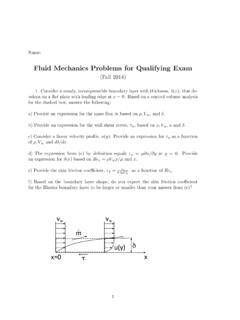
7 This term is either the head lost to friction hL or the pressure loss pL. L22222111hg2uzhg2uzh+++=++ The pressure form of the equation is as follows. L22222111p2ugzp2ugzp+ + += + + The total energy of the FLUID (excluding internal energy) is no longer constant. Note that if a point is a free surface the pressure is normally atmospheric but if gauge pressures are used, the pressure and pressure head becomes zero. Also, if the surface area is large (say a large tank), the velocity of the surface is small and when squared becomes negligible so the kinetic energy term is neglected (made zero). 5 WORKED EXAMPLE No. 1 The diagram shows a pump delivering water through as pipe 30 mm bore to a tank. Find the pressure at point (1) when the flow rate is dm3/s.
8 The density of water is 1000 kg/m3. The loss of pressure due to friction is 50 kPa. SOLUTION Area of bore A = x = x 10-6 m2. Flow rate Q = dm3/s = m3/s Mean velocity in pipe = Q/A = m/s Apply Bernoulli between point (1) and the surface of the tank. Lpugzpugzp+++=++2222222111 Make the low level the datum level and z1 = 0 and z2 = 25. The pressure on the surface is zero gauge pressure. PL = 50 000 Pa The velocity at (1) is m/s and at the surface it is zero. pressure gauge +++=++ 6 WORKED EXAMPLE 2 The diagram shows a tank that is drained by a horizontal pipe. Calculate the pressure head at point (2) when the valve is partly closed so that the flow rate is reduced to 20 dm3/s. The pressure loss is equal to 2 m head. SOLUTION Since point (1) is a free surface, h1 = 0 and u1 is assumed negligible.
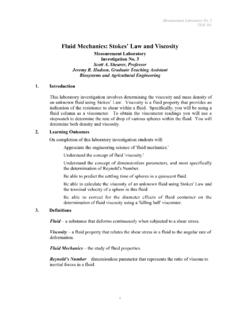
9 The datum level is point (2) so z1 = 15 and z2 = 0. Q = m3/s A2 = d2/4 = x ( )/4 = x 10-3 m2. u2 = Q/A = x 10-3 = m/s Bernoulli s equation in head form is as follows. x +++=+++++=++ 7 WORKED EXAMPLE 3 The diagram shows a horizontal nozzle discharging into the atmosphere. The inlet has a bore area of 600 mm2 and the exit has a bore area of 200 mm2. Calculate the flow rate when the inlet pressure is 400 Pa. Assume there is no energy loss. Fig. SOLUTION Apply Bernoulli between (1) and (2) L22222111p2 u gzp2 u gzp+++=++ Using gauge pressure, p2 = 0 and being horizontal the potential terms cancel. The loss term is zero so the equation simplifies to the following. 2 u2 up22211=+ From the continuity equation we have Q 000 510 x 110 x 600 QAQu6-226-11====== Putting this into Bernoulli s equation we have the following.
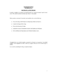
10 ()()/scm /sm 10 x x1036 x x1000400336-99229292922=====+=+ 8 HYDRAULIC GRADIENT Consider a tank draining into another tank at a lower level as shown. There are small vertical tubes at points along the length to indicate the pressure head (h). Relative to a datum, the total energy head is hT = h + z + u2/2g and this is shown as line A. The hydraulic grade line is the line joining the free surfaces in the tubes and represents the sum of h and z only. This is shown as line B and it is always below the line of hT by the velocity head u2/2g. Note that at exit from the pipe, the velocity head is not recovered but lost as friction as the emerging jet collides with the static liquid. The free surface of the tank does not rise. The only reason why the hydraulic grade line is not horizontal is because there is a frictional loss hf.