Transcription of FLUID MECHANICS TUTORIAL No. 3 BOUNDARY LAYER …
1 1 FLUID MECHANICS TUTORIAL No. 3 BOUNDARY LAYER THEORY In order to complete this TUTORIAL you should already have completed TUTORIAL 1 and 2 in this series. This TUTORIAL examines BOUNDARY LAYER theory in some depth. When you have completed this TUTORIAL , you should be able to do the following. Discuss the drag on bluff objects including long cylinders and spheres. Explain skin drag and form drag. Discuss the formation of wakes. Explain the concept of momentum thickness and displacement thickness. Solve problems involving laminar and turbulent BOUNDARY layers. Throughout there are worked examples, assignments and typical exam questions. You should complete each assignment in order so that you progress from one level of knowledge to another. Let us start by examining how drag is created on objects. 2 1. DRAG When a FLUID flows around the outside of a body, it produces a force that tends to drag the body in the direction of the flow.
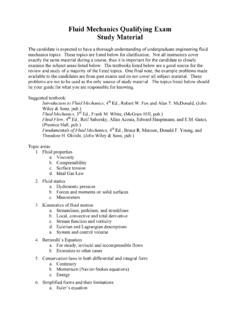
2 The drag acting on a moving object such as a ship or an aeroplane must be overcome by the propulsion system. Drag takes two forms, skin friction drag and form drag. SKIN FRICTION DRAG Skin friction drag is due to the viscous shearing that takes place between the surface and the LAYER of FLUID immediately above it. This occurs on surfaces of objects that are long in the direction of flow compared to their height. Such bodies are called STREAMLINED. When a FLUID flows over a solid surface, the LAYER next to the surface may become attached to it (it wets the surface). This is called the no slip condition . The layers of FLUID above the surface are moving so there must be shearing taking place between the layers of the FLUID . The shear stress acting between the wall and the first moving LAYER next to it is called the wall shear stress and denoted w.
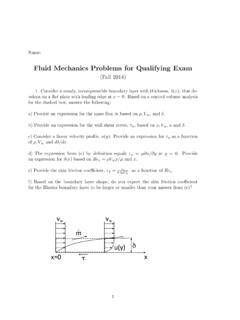
3 The result is that the velocity of the FLUID u increases with height y. The BOUNDARY LAYER thickness is taken as the distance required for the velocity to reach 99% of uo. This LAYER is called the BOUNDARY LAYER and is the BOUNDARY LAYER thickness. Fig. Shows how the velocity "u" varies with height "y" for a typical BOUNDARY LAYER . In a pipe, this is the only form of drag and it results in a pressure and energy lost along the length. A thin flat plate is an example of a streamlined object. Consider a stream of FLUID flowing with a uniform velocity uo. When the stream is interrupted by the plate (fig. ), the BOUNDARY LAYER forms on both sides. The diagram shows what happens on one side only. Fig. The BOUNDARY LAYER thickness grows with distance from the leading edge. At some distance from the leading edge, it reaches a constant thickness.
4 It is then called a FULLY DEVELOPED BOUNDARY LAYER . 3 The Reynolds number for these cases is defined as: =xu)R(oxe x is the distance from the leading edge. At low Reynolds numbers, the BOUNDARY LAYER may be laminar throughout the entire thickness. At higher Reynolds numbers, it is turbulent. This means that at some distance from the leading edge the flow within the BOUNDARY LAYER becomes turbulent. A turbulent BOUNDARY LAYER is very unsteady and the streamlines do not remain parallel. The BOUNDARY LAYER shape represents an average of the velocity at any height. There is a region between the laminar and turbulent section where transition takes place The turbulent BOUNDARY LAYER exists on top of a thin laminar LAYER called the LAMINAR SUB LAYER . The velocity gradient within this LAYER is linear as shown. A deeper analysis would reveal that for long surfaces, the BOUNDARY LAYER is turbulent over most of the length.
5 Many equations have been developed to describe the shape of the laminar and turbulent BOUNDARY layers and these may be used to estimate the skin friction drag. Note that for this ideal example, it is assumed that the velocity is the undisturbed velocity uo everywhere outside the BOUNDARY LAYER and that there is no acceleration and hence no change in the static pressure acting on the surface. There is hence no drag force due to pressure changes. CALCULATING SKIN DRAG The skin drag is due to the wall shear stress w and this acts on the surface area (wetted area). The drag force is hence: R = w x wetted area. The dynamic pressure is the pressure resulting from the conversion of the kinetic energy of the stream into pressure and is defined by the expression 2u2o .The drag coefficient is defined as u2area x wetteduR2 Carea d x wettepressure dynamicforce DragC20w20 DfDf = == Note that this is the same definition for the pipe friction coefficient Cf and it is in fact the same thing.
6 It is used in the Darcy formula to calculate the pressure lost in pipes due to friction. For a smooth surface, it can be shown that CDf = (Re)x-1/5 (Re)x is the Reynolds number based on the length. =Lu)R(oxe 4 WORKED EXAMPLE Calculate the drag force on each side of a thin smooth plate 2 m long and 1 m wide with the length parallel to a flow of FLUID moving at 30 m/s. The density of the FLUID is 800 kg/m3 and the dynamic viscosity is 8 cP. SOLUTION N 1 x 2 x Area x Wetted RPa 10 x 360 x pressure dynamic x C kPa 360 230 x 800 2u pressure ) x10(6 x C10 x 6 x 30 x 800 Lu)R(w3 Dfw220516Df6oxe== ==== == ===== = On a small area the drag is dR = w dA. If the body is not a thin plate and has an area inclined at an angle to the flow direction, the drag force in the direction of flow is w dA cos . The drag force acting on the entire surface area is found by integrating over the entire area.
7 =dA cosRw Solving this equation requires more advanced studies concerning the BOUNDARY LAYER and students should refer to the classic textbooks on this subject. SELF ASSESSMENT EXERCISE No. 1 1. A smooth thin plate 5 m long and 1 m wide is placed in an air stream moving at 3 m/s with its length parallel with the flow. Calculate the drag force on each side of the plate. The density of the air is kg/m3 and the kinematic viscosity is x 10-5 m2/s. ( N) 2. A pipe bore diameter D and length L has fully developed laminar flow throughout the entire length with a centre line velocity uo. Given that the drag coefficient is given as CDf = 16/Re where =DuReo, show that the drag force on the inside of the pipe is given as R=8 uoL and hence the pressure loss in the pipe due to skin friction is pL = 32 uoL/D2 5 FORM DRAG and WAKES Form or pressure drag applies to bodies that are tall in comparison to the length in the direction of flow.
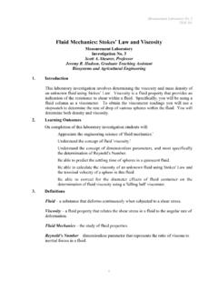
8 Such bodies are called BLUFF BODIES. Consider the case below that could for example, be the pier of a bridge in a river. The water speeds up around the leading edges and the BOUNDARY LAYER quickly breaks away from the surface. Water is sucked in from behind the pier in the opposite direction. The total effect is to produce eddy currents or whirl pools that are shed in the wake. There is a build up of positive pressure on the front and a negative pressure at the back. The pressure force resulting is the form drag. When the breakaway or separation point is at the front corner, the drag is almost entirely due to this effect but if the separation point moves along the side towards the back, then a BOUNDARY LAYER forms and skin friction drag is also produced. In reality, the drag is always a combination of skin friction and form drag. The degree of each depends upon the shape of the body.
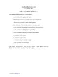
9 The next diagram typifies what happens when FLUID flows around a bluff object. The FLUID speeds up around the front edge. Remember that the closer the streamlines, the faster the velocity. The line representing the maximum velocity is shown but also remember that this is the maximum at any point and this maximum value also increases as the stream lines get closer together. 6 Two important effects affect the drag. Outside the BOUNDARY LAYER , the velocity increases up to point 2 so the pressure acting on the surface goes down. The BOUNDARY LAYER thickness gets smaller until at point S it is reduced to zero and the flow separates from the surface. At point 3, the pressure is negative. This change in pressure is responsible for the form drag. Inside the BOUNDARY LAYER , the velocity is reduced from umax to zero and skin friction drag results. In problems involving liquids with a free surface, a negative pressure shows up as a drop in level and the pressure build up on the front shows as a rise in level.
10 If the object is totally immersed, the pressure on the front rises and a vacuum is formed at the back. This results in a pressure force opposing movement (form drag). The swirling flow forms vortices and the wake is an area of great turbulence behind the object that takes some distance to settle down and revert to the normal flow condition. Here is an outline of the mathematical approach needed to solve the form drag. Form drag is due to pressure changes only. The drag coefficient due to pressure only is denoted CDp and defined as area projected x uR2 Carea projected x pressure dynamicforce DragC20 DpDp == The projected area is the area of the outline of the shape projected at right angles to the flow. The pressure acting at any point on the surface is p. The force exerted by the pressure on a small surface area is p dA. If the surface is inclined at an angle to the general direction of flow, the force is p cos dA.