Transcription of FLUID MECHANICS TUTORIAL No.8A WATER TURBINES
1 1 FLUID MECHANICS TUTORIAL WATER TURBINES When you have completed this TUTORIAL you should be able to Explain the significance of specific speed to turbine selection. Explain the general principles of Pelton Wheels Kaplan TURBINES Francis Turbine Construct blade vector diagrams for moving vanes for a Pelton Wheels and a Francis Turbine Deduce formulae for power and efficiency for TURBINES .
2 Solve numerical problems for a Pelton Wheels and a Francis Turbine 1. INTRODUCTION A WATER turbine is a device for converting WATER ( FLUID ) power into shaft (mechanical) power. A pump is a device for converting shaft power into WATER power. Two basic categories of machines are the rotary type and the reciprocating type. Reciprocating motors are quite common in power hydraulics but the rotary principle is universally used for large power devices such as on hydroelectric systems. Large pumps are usually of the rotary type but reciprocating pumps are used for smaller applications. THE SPECIFIC SPEED FOR VARIOUS TYPES OF TURBINES The power 'P' of any rotary hydraulic machine (pump or motor) depends upon the density ' ' , the speed 'N', the characteristic diameter 'D', the head change ' H', the volume flow rate 'Q' and the gravitational constant 'g'.
3 The general equation is: P = f( , N, D, H, Q, g) It is normal to consider g H as one quantity. P = f{ , N, D, (g H),Q} There are 6 quantities and 3 dimensions so there are three dimensionless groups 1, 2and 3. First form a group with P and ND. ()()()()tCoefficienPower DN P DN P5c c 3- c-3a2 Length 3b b3 Time a1 MassDTMLTLMDN ND P5315311c1b1a3321cba1====+=+== = ==== Next repeat the process between Q and ND ()()()()tCoefficien Flow NDQ DN Q3c c-3a3 Length a0 Mass 1b b1- TimeDTMLTMDN ND Q323102c1b1a313cba2====+=== ==== Next repeat the process between g H and ND ()()()()tCoefficien Head DNQ DN Q2c c-3a2 Length 2b b2- Time a0 MassDTMLTLMDN ND H)
4 (g2232203c1b1a3220cba3====+== ===== Finally the complete equation is =22253DN H gNDQ D NP 2 SPECIFIC SPEED Ns The specific speed is a parameter used for pumps and TURBINES to determine the best design to match a given pumped system. The formula may be derived from consideration of the pump geometry or by dimensional analysis. The latter will be used here. =22253DN H gNDQ D NP The three dimensionless numbers represent the Power coefficient, the flow coefficient and the Head coefficient respectively. Now consider a family of geometrically similar machines operating at dynamically similar conditions.)
5 For this to be the case the coefficients must have the same values for each size. Let the 3 coefficients be 1, 2 and 3 such that 4321s21432121214323312132312121312213323 12131312312132132312213222331232531 H) (NQN constant K H) (NQ QK H) (NKQ H) (NKQ H) ( constant g NQ H) (N Q H gN1 N H gN Q Equating N H gD DN H g N Q D NDQ D NP ===== ==== = == === Ns is a dimensionless parameter that and the units used are normally rev/min for speed, m3/s for flow rate and metres for head. Other units are often used and care should be taken when quoting Ns values. It follows that for a given speed, the specific speed is large for large flows and low heads and small for small flows and large heads.
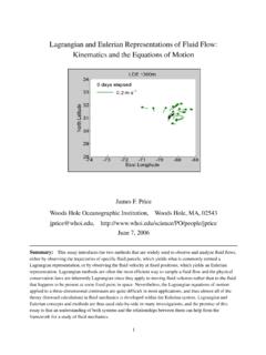
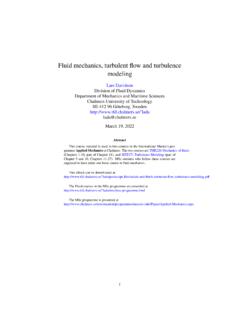
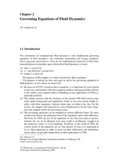
6 The important value is the one that corresponds to the conditions that produce the greatest efficiency. The diagram illustrates how the design affects the specific speed. Figure 1 3 4 2. GENERAL PRINCIPLES OF TURBINES . WATER POWER This is the FLUID power supplied to the machine in the form of pressure and volume. Expressed in terms of pressure head the formula is = mg H M is the mass flow rate in kg/s and H is the pressure head difference over the turbine in metres.
7 Remember that p = g H Expressed in terms of pressure the formula is = Q p Q is the volume flow rate in m3/s. p is the pressure drop over the turbine in N/m2 or Pascals. SHAFT POWER This is the mechanical, power output of the turbine shaft. The well known formula is = 2 NT Where T is the torque in Nm and N is the speed of rotation in rev/s DIAGRAM POWER This is the power produced by the force of the WATER acting on the rotor. It is reduced by losses before appearing as shaft power. The formula for depends upon the design of the turbine and involves analysis of the velocity vector diagrams. HYDRAULIC EFFICIENCY This is the efficiency with which WATER power is converted into diagram power and is given by hyd= MECHANICAL EFFICIENCY This is the efficiency with which the diagram power is converted into shaft power.
8 The difference is the mechanical power loss. mech= OVERALL EFFICIENCY This is the efficiency relating FLUID power input to shaft power output. o/a= It is worth noting at this point that when we come to examine pumps, all the above expressions are inverted because the energy flow is reversed in direction. The WATER power is converted into shaft power by the force produced when the vanes deflect the direction of the WATER . There are two basic principles in the process, IMPULSE and REACTION. IMPULSE occurs when the direction of the FLUID is changed with no pressure change. It follows that the magnitude of the velocity remains unchanged. REACTION occurs when the WATER is accelerated or decelerated over the vanes.
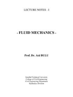
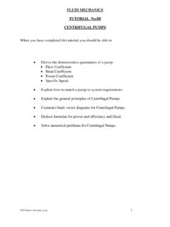
9 A force is needed to do this and the reaction to this force acts on the vanes. Impulsive and reaction forces are determined by examining the changes in velocity (magnitude and direction) when the WATER flows over the vane. The following is a typical analysis. The vane is part of a rotor and rotates about some centre point. Depending on the geometrical layout, the inlet and outlet may or may not be moving at the same velocity and on the same circle. In order to do a general study, consider the case where the inlet and outlet rotate on two different diameters and hence have different velocities. u1 is the velocity of the blade at inlet and u2 is the velocity of the blade at outlet.
10 Both have tangential directions. 1 is the relative velocity at inlet and 2 is the relative velocity at outlet. The WATER on the blade has two velocity components. It is moving tangentially at velocity u and over the surface at velocity . The absolute velocity of the WATER is the vector sum of these two and is denoted v. At any point on the vane v = + u At inlet, this rule does not apply unless the direction of v1 is made such that the vector addition is true. At any other angle, the velocities will not add up and the result is chaos with energy being lost as the WATER finds its way onto the vane surface. The perfect entry is called "SHOCKLESS ENTRY" and the entry angle 1 must be correct.