Transcription of FLUID MECHANICS TUTORIAL No.8B CENTRIFUGAL PUMPS
1 1 FLUID MECHANICS TUTORIAL CENTRIFUGAL PUMPS When you have completed this TUTORIAL you should be able to Derive the dimensionless parameters of a pump Flow Coefficient Head Coefficient Power Coefficient Specific Speed. Explain how to match a pump to system requirements. Explain the general principles of CENTRIFUGAL PUMPS . Construct blade vector diagrams for CENTRIFUGAL PUMPS . Deduce formulae for power and efficiency and Head. Solve numerical problems for CENTRIFUGAL PUMPS .
2 1. DIMENSIONAL ANALYSIS The power 'P' of any rotary hydraulic pump depends upon the density ' ' , the speed 'N', the characteristic diameter 'D', the head change ' H', the volume flow rate 'Q' and the gravitational constant 'g'. The general equation is: P = f( , N, D, H, Q, g) It is normal to consider g H as one quantity. P = f{ , N, D, (g H),Q} There are 6 quantities and 3 dimensions so there are three dimensionless groups 1, 2and 3. First form a group with P and ND. ()()()()tCoefficienPower DN P DN P5c c 3- c-3a2 Length 3b b3 Time a1 MassDTMLTLMDN ND P5315311c1b1a3321cba1====+=+== = ==== Next repeat the process between Q and ND ()()()()tCoefficien Flow NDQ DN Q3c c-3a3 Length a0 Mass 1b b1- TimeDTMLTMDN ND Q323102c1b1a313cba2====+=== ==== Next repeat the process between g H and ND ()()()()
3 TCoefficien Head DNQ DN Q2c c-3a2 Length 2b b2- Time a0 MassDTMLTLMDN ND H) (g2232203c1b1a3220cba3====+== ===== Finally the complete equation is =22353DN H gNDQ D NP 2 SPECIFIC SPEED Ns The specific speed is a parameter used for PUMPS and turbines to determine the best design to match a given pumped system. The formula may be derived from consideration of the pump geometry or by dimensional analysis.
4 The latter will be used here. =22253DN H gNDQ D NP The three dimensionless numbers represent the power coefficient, the flow coefficient and the head coefficient respectively. Now consider a family of geometrically similar machines operating at dynamically similar conditions. For this to be the case the coefficients must have the same values for each size. Let the 3 coefficients be 1, 2 and 3 such that constant K H) (NQ QK H) (NKQ H) (NKQ H) ( constant g NQ H) (N Q H gN1 N H gN Q Equating N H gD DN H g N Q D NDQ D NP 2143212121432331213231212131221332312131 312312132132312213222331232531==== ==== = == === This constant is called the Specific Speed 4321 H)
5 (NQNs= Ns is a dimensionless parameter that and the units used are normally rev/min for speed, m3/s for flow rate and metres for head. Other units are often used and care should be taken when quoting Ns values. It follows that for a given speed, the specific speed is large for large flows and low heads and small for small flows and large heads. The important value is the one that corresponds to the conditions that produce the greatest efficiency. 3 2.)
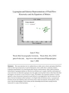
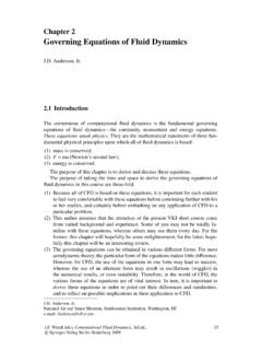
6 MATCHING PUMPS TO SYSTEM REQUIREMENTS The diagram shows a typical relationship between the head and flow of a given CF pump at a given speed. Figure 1 The Ns value may be calculated using the flow and head corresponding to the maximum efficiency at point A. SELECTING PUMP SIZE The problem is that the optimal point of any given pump is unlikely to correspond to the system requirements for example at point B. What we should do ideally is find a geometrically similar pump that will produce the required head and flow at the optimal point. The geometrically similar pump will run under dynamically similar conditions so it follows that the specific speed Ns is the same for both PUMPS at the optimal point.
7 The procedure is to first calculate the specific speed of the pump using the flow and head at the optimal conditions. 43A21 AAsHQNN= Suppose point B is the required operating point defined by the system. 43B21 BBsHQNN= Equating, we can calculate NB, the speed of the geometrically similar pump. We still don t know the size of the pump that will produce the head and flow at B. Since the head and flow coefficients are the same then:- Equating Flow Coefficients we get 1/3 BAABABNQNQDD = Equating head coefficients we get we get ABBABHH NND= If the forgoing is correct then both will give the same answer.
8 4 WORKED EXAMPLE No. 1 A CENTRIFUGAL pump is required to produce a flow of water at a rate of m3/s against a total head of m. The operating characteristic of a pump at a speed of 1430 rev/min and a rotor diameter of 125 mm is as follows. Efficiency 0 48 66 66 45 % QA 0 m3/s HA 72 m Determine the correct size of pump and its speed to produce the required head and flow.
9 SOLUTION Plot the data for the pump and determine that the optimal head and flow are 65 m and Calculate Ns at point A x 1430 HQNN3/41/243A21 AAs=== Calculate the Speed for a geometrically similar pump at the required conditions. rev/min x Next calculate the diameter of this pump. mm 1011216 x x = = or mm 12161430 x 251HH NNDDABBAAB=== Answer:- we need a pump 101 mm diameter running at 1216 rev/min. 5 RUNNING WITH THE WRONG SIZE In reality we are unlikely to find a pump exactly the right size so we are forced to use the nearest we can get and adjust the speed to obtain the required flow and head.
10 Let B be the required operating point and A the optimal point for the wrong size pump. We make the flow and head coefficients the same for B and some other point C on the operating curve. The diameters cancel because they are the same. 3 CCC3 BBBDNQDNQ= CBCBNNQQ= 2C2CA2C2 CCDNH gDNH g= 2C2 BCBN NHH= Substitute ABABQQNN=to eliminate the speed 6 2 BCBCQQHH = This is a family of parabolic curves starting at the origin. If we take the operating point B we can determine point C as the point where it intersects the operating curve at speed A.