Transcription of FLY.BY-WIRE FLIGHT CONTROL SYSTEMS
1 : FLIGHT CONTROL SYSTEMS . BY. mkOk '. SUTHEN&D- (CAP). J:4'Taik Er&cc2. AIr Fo=c M&~gh Dpm=lic !Labortaoi (FDCL). W era Afr Forme Batc OWi 8 SEPTEMBER 1968. This document has been approved for pub-L. lie release; its distributi6n is unlirited. Preparedfor Joint Meeting of FLIGHT Mechanics and Guidance and CONTROL Panels of AGARD. Oslo, Norway C.) C . ,:LEA fN C HOUSE 'E. 22 L2 7. AD 679 i158. FLY-BY- wire FLIGHT CONTROL SYSTEMS . J. P. Sutherland , Air Force FLIGHT Dynamics Laboratory Wright Patterson Air Force Base, Ohio 3 September 1968. )4: K j. I. Iq FLY-BY- wire FLIGHT COINTROL SYSTEMS . Introduction ;>The purpose of this paper is to provide the reader with an intro- duction to fly-by- wire and an outline of state-of-the-art fly-by- wire techniqui-s. An outline of the philosophy of fly-by- wire FLIGHT CONTROL SYSTEMS is given, the evolution of fly-by- wire is discussed, the ad- vantages of fly-by- wire over mechanical SYSTEMS are listed, current fly-by- wire techniques are outlined, and a brief review of,the Air force FLIGHT Dynamics Laboratory proposedcin-house and contracted fly-by- wire development programs is given.
2 '. The Philosophy of Fly-by- wire Before discussing fly-by- wire , it is important to understand what is meant by the term "fly-by- wire ". Two other terms, "electrical primary FLIGHT CONTROL system " and "pseudo fly-by- wire ", are often used in discussions of fly-by- wire and therefore also require definition. The following definitions of these three terms apply throughout this paper and have been generally accepted by the Air Force FLIGHT Dynamics Laboratory. Electrical Primary FLIGHT CONTROL system (EPFCS) - A FLIGHT CONTROL system mechanization wherein the pilot's CONTROL commands are transmitted to the moment or force p/roducer only via electrical wires. Fly-by- wire - A fly-by- wire FLIGHT CONTROL system is an electrical primary FLIGHT CONTROL system employing feedback such that vehicle motion is the controlled parameter.
3 Pseudo Fly-by- wire - A fly-by- wire FLIGHT CONTROL system with a normally disengaged mechanical backup. Fly-by- wire , that is, the complete replacement of the mechanical linkages between the pilot's stick and the CONTROL surface actuators by electrical signal wires, offers a convenient and logical solution to many of the CONTROL system problems associated with modern high performance aircraft and aerospace vehicles. However, there exists a strong reluctance on the part of both pilots and FLIGHT CONTROL system designers to remove all FLIGHT CONTROL cables and mechanical linkages and rely solely on electrical signals and electronic devices. Nor is this reluctance unreasonable. Since the Wright Brothers first flew at Kittyhawk in 1903, there has been some form of direct mechanical linkage between the pilot and the CONTROL surfaces or CONTROL surface actuators.
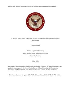
4 The succesaful use of such SYSTEMS has resulted in the growth of a sense of security toward mechanical CONTROL linkages which now tends to inhibit fly-by- wire development. "Security is a mechanical K. FLIGHT CONTROL system " quips Snoopy as he pursues the Red Barron (Figure 1). Yet in today's high performance aircraft, security is ci I. c~n >m. (,). -J. 4 0. z (I~O. H. Ii *1. I ..%%. H. I w rz H. 4 e t I. 4 2. i _____ _____. -1 - definitely not a mechanical CONTROL system . Instead, security is having a reliable Stability Augmentation system (SAS). For without SAS many high performance aircraft are only marginally stable and must, therefore, rely on electronic devices (black boxes) for the successful completion of a mission. In such cases, an effort has been made to obtain some of the advantages of fly-by- wire without losing the "security" of a mechanical system with the result that many of the disadvantages of the mechanical systea axe retained.)
5 '- A. The state-of-the-art in electronic circuits and redundancy techniques has now antiquated this approach. It is now possible to talk realistic- ally about building a pure fly-by- wire FLIGHT CONTROL system that is more reliable than its mechanical counterpart. Until it is actually done, however, and successfully demorstrated in FLIGHT tests, the Missourian in many of us will prevail and the security stigma associated with mechanical CONTROL SYSTEMS will predominate. Our fly-by- wire effort is orientated towards fulfilling this need. The Evolution of Fly-by- wire The concept of fly-by- wire is not something which sprung up over night, but rather it evolved slowly through the years as aircraft FLIGHT CONTROL system requirements changed. With progressive increases . in aircraft size and speed, power-boosted CONTROL quickly became a requirement in order to enable the pilot to utilize the full maneuver capability of the aircraft.
6 Hydraulic boost, wh'ere a hydraulic actu- ator is connected in parallel to add to the pilot's force on the CONTROL cables, is still used on many aircraft; for example, the B-47, T-33, 707 rudder, and 727 elevators and ailerons. Shortly after World War II, fully powered controls came into being. Here the CONTROL cables from the pilot's stick are attached direc!y to the spool of the servo valve on the actuator and are in no way physically connected to the CONTROL surface Feel is introduced into the systen artificially with springs, dash pots, bob weights, and in some :ases "q"bellows. This artificial feel, while not required in moving the CONTROL surfaces, is needed to give the pilot the proper handling quelities characteristics for CONTROL of the aircraft. Hence, although the pilot has no direct physical connection with the CONTROL surfaces, the artificial feel system gives him the impression that he has.
7 Examples of aircraft using fully powered controls are the F-86, F-4C, F-104, F-105, and 727 rudder. One of the primary reasons for using fully powered cont-ol is that in the transonic region the forces on the surfaces vary gi-atly and are highly nonlinear. The resulting stick forces with direct mechanical connection to the CONTROL surfaces were unacceptable from a handling qualities point of view. Fully powered controls are inherently irreversible and thus unaffected by nonlinearities in the transonic region, allowing the artificial feel system to be designed to give smooth transition from subsonic to supersonic FLIGHT . K. 'i d As aircraft continued to increase in size ant performance, it became necessary to add stability augmentation to assist the pilot in his CONTROL task. Stability augmentation SYSTEMS (SAS), having very limited authority, were added in series with the normal FLIGHT CONTROL system .
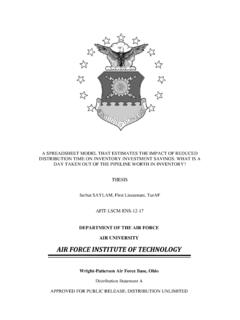
8 For some aircraft in certain FLIGHT regimes, however, the proper functioning of the SAS was required for the very survival of the aircraft. The success of SAS led to the introduction of CAS, CONTROL Augmentation system . A CONTROL augmentation system has an electrical system operating in parallel with the mechanical CONTROL system . The electrical system predominates by virtue of its high gain and servo authority and performs essentially as a fly-by- wire system . The step from CAS to pseudo fly-by- wire is a small one and involves declutching the mechanical system when it is not in use. To get a fly-by- wire system from a pseudo fly-by- wire system , one needs only to remove the mechanical FLIGHT CONTROL system entirely. Fly-by- wire FLIGHT CONTROL SYSTEMS are currently used in some space vehicles. Figure 2 illustrates the SAS to CAS to FBW evolution.
9 Need for and Advantages of Fly-by- wire The FLIGHT CONTROL SYSTEMS of yesteryear, which consisted of relatively simple direct mechanical linkages, cables, and feel springs, can no longer meet the demands of advanced aircraft CONTROL system requiretents. The FLIGHT CONTROL designer has been forced to replace the simple manual CONTROL system witl: complex nonlinear linkages, mix- Ii ing assemblies, power actuation devices, and active artificial feel SYSTEMS containing literally hundreds of different parts and inter- connections. In his struggle to meet rigid performance and environ- mental requirements (such as immunity to aircraft structural changes due to flexing and thermal expansion) the designer has been confined by the requirements for low weight and high reliability. Hence, a compromise is forced and the full potential of many aircraft is never realized because of the resulting CONTROL system limitations.
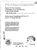
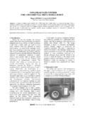
10 The degree of complexity to which FLIGHT CONTROL designers have had to go in their effort to solve these proolems is best i'lustrated by an examination of Figure 3 which depicts a portion of the FLIGHT CONTROL * system of a typical high performance tactical fighter aircraft. You will note that the system is made up of a great number of relatively heavy push rods, bell cranks, and other linkages with a total of one hundred and fourteen bearing points. Each bearing point represents a source of fri tion and a possible failure point. Nor is the complexity of this example FLIGHT CONTROL system illustrated in Figure 3 unique. The B-70 FLIGHT CONTROL system is even more complex but would require such a large foldout to display that one might say it is beyond the scope of this paper. Helicopter FLIGHT CONTROL SYSTEMS are also enormously complex and their problems were multiplied several fold with the introduction of V/STOL aircraft.